Technical Description, Installation Instructions, Operation
21
DP/AS-Interface Link 20E
Release 11/2002
C79000-G8976-C138–04
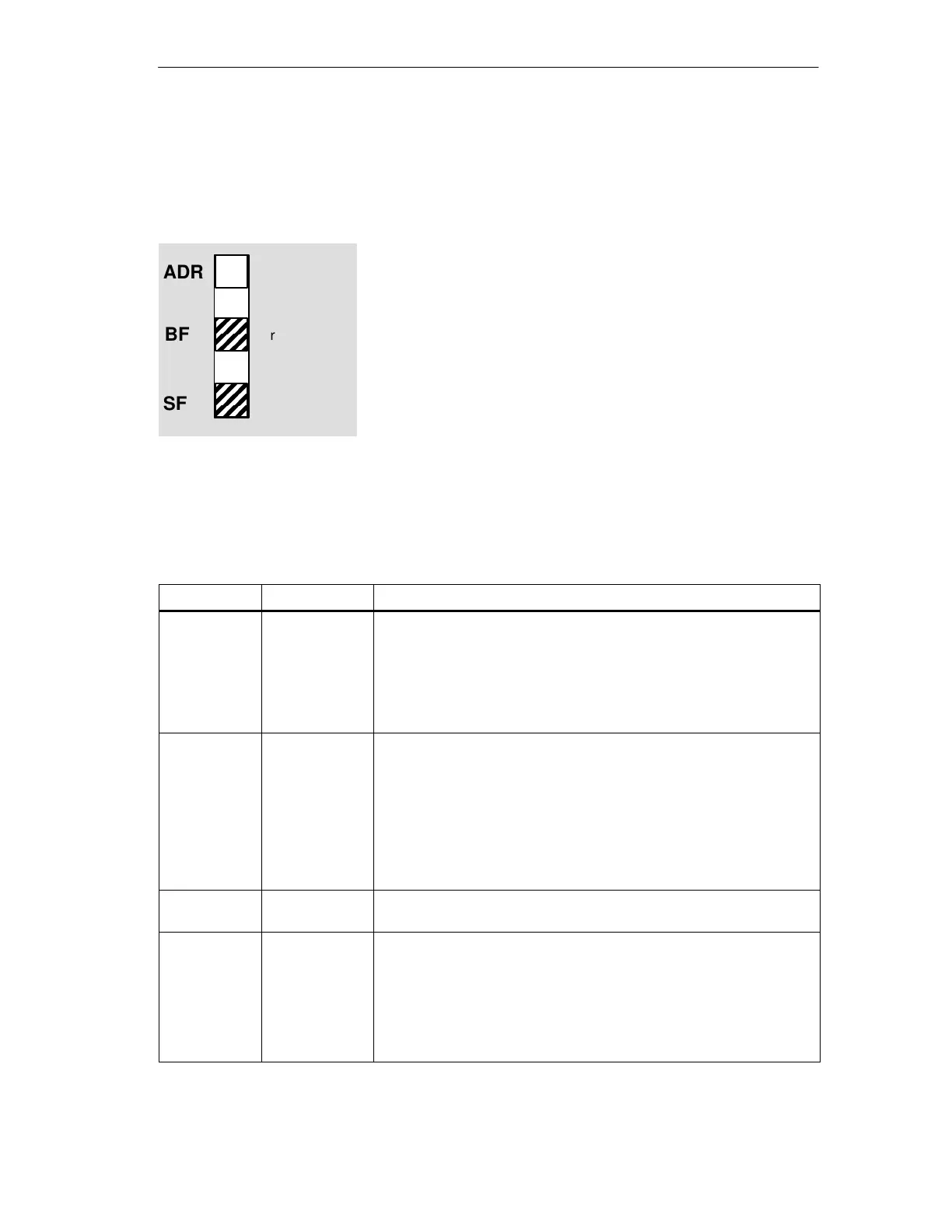
1.7.1 Status Display
Interpreting the Status Display
The status display is the default standard display in the
basic status of the DP/AS-i Link 20E module. No group
LED is lit green. The “ADR” LED must also not be lit red.
The lower 7 LEDs indicate the status of the
DP/AS-i Link 20E; the label to the right of the LEDs then
applies.
The bottom 5 LEDs indicate errors/states on the
AS-Interface. The BF LED indicates an error on
PROFIBUS-DP
Meaning of the 7 Lower LEDs
When the status display is active, the LEDs have the following significance:
Table 1-2
LED (color)
Status Meaning
BF (red) Bus Failure Indicates errors on PROFIBUS DP.
The LED is lit when:
S The connection between the DP master and the DP/AS-i Link 20E
module has broken down or the DP master is not active.
S The DP/AS-i Link 20E module was not or was incorrectly
configured/assigned parameters by the DP master.
SF (red) System error The LED is lit when:
S In the protected mode, a diagnostic interrupt (entering state) was
triggered on the DP master.
S The DP/AS-i Link 20E has detected an internal error (for example
EEPROM defective).
S While pressing the SET button, the DP/AS-i Link 20E module
cannot currently make the required mode change (for example a
slave exists with address 0).
PWR (green) Run The LED is lit when the DP/AS-Interface Link 20E is supplied with
power.
APF (red) AS-i Power Fail This indicates that the voltage supplied to the AS-i cable by the AS-i
power supply unit is too low.
Note:
The DP/AS-i Link 20E module is supplied with power entirely from the
AS-Interface. Total failure of the AS-i power supply can therefore no
longer be displayed by AS-i Power Fail. You can recognize this
situation because the “PWR” LED is not lit.
ADR
BF
SF
red or off
off
red or off
 Loading...