EasyManua.ls Logo

Siemens DP/AS-Interface Link 20E User Manual

Siemens DP/AS-Interface Link 20E
160 pages
To Next Page IconTo Next Page
To Previous Page IconTo Previous Page
Page #96 background imageLoading...
Page #96 background image
Using the Command Interface
96
DP/AS-Interface Link 20E
Release 11/2002
C79000-G8976-C138–04
3.3.15 Get_AS-i_Slave_Status
Purpose
With this call, the status register of the addressed AS-i slave can be read out.
Depending on the type of AS-i slave, the flags of the status register have the
following meaning:
Status
Bit
AS-i slave complying with standard 2.0 AS-i slave complying with standard
2.1
S 0 Address volatile Address/ID code volatile
This flag is set when
S the internal slave routine for permanent storage of the AS-i slave address is
active. This can take up to 15 ms and must not be interrupted by a further
addressing call.
S the AS-i internal slave address comparison recognizes that the stored
address is not the same as the entry in the address register.
S 1 Parity error detected
This flag is set when the AS-i slave has
recognized a parity error in a received
frame since the last “read and delete
status” job.
I/O error detected
An AS-i slave can set this flag
when it has detected and error (for
example wire break) in the attached
I/Os.
S 2 End bit error detected
This flag is set when the AS-i slave has
recognized an end bit error in a frame
since the last “read and delete status” job.
reserved
S 3 Read error in non-volatile memory
This bit is set when the AS-i slave has detected a read error when reading the
non-volatile memory.
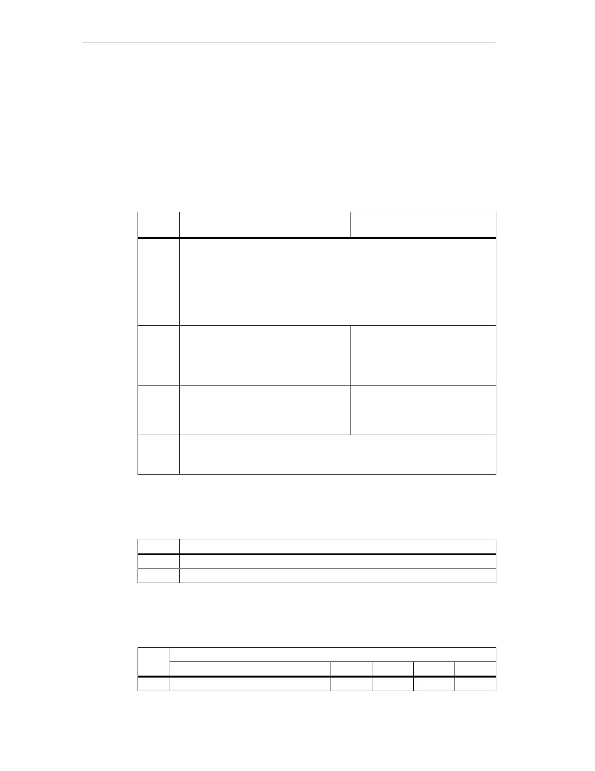
Structure of the Job Data in the Send Buffer
Byte Meaning
0 Command number: 0F
H
1 Slave address
Structure of the Response Data in the Receive Buffer
Byte Meaning
Bit 7 Bit 4 Bit 3 Bit 2 Bit 1 Bit 0
0 0 S 3 S 2 S 1 S 0

Table of Contents

Question and Answer IconNeed help?

Do you have a question about the Siemens DP/AS-Interface Link 20E and is the answer not in the manual?

Siemens DP/AS-Interface Link 20E Specifications

General IconGeneral
BrandSiemens
ModelDP/AS-Interface Link 20E
CategoryComputer Hardware
LanguageEnglish

Summary

Technical Description, Installation Instructions, Operation

General Notes on Operation – Safety Warnings

Essential safety precautions and guidelines for operating the DP/AS-i Link 20E module.

Installing the Module

Step-by-step instructions for mounting and installing the DP/AS-i Link 20E module on a standard rail.

Display and Control Elements

Explanation of the LEDs (ADR, BF, SF) and buttons (SET, DISPLAY) on the module's front panel.

Configuring the AS-Interface with the SET Button (Button Configuration)

Guide to commissioning the AS-Interface using the SET button for quick configuration.

Configuring the DP/AS-i Link 20E as a DP Slave on the DP Master

Process of setting up the DP/AS-i Link 20E as a DP slave on a PROFIBUS DP master.

Configuration in STEP 7 – Basic Configuration

Steps for basic configuration of the DP/AS-i Link 20E within STEP 7 HW Config.

Data Exchange Between the DP Master and AS-i Slave

Transferring AS-i Binary Values

Explains how to access binary inputs and outputs of AS-i slaves via the DP master in cyclic mode.

Addressing AS-i Slaves

Information on addressing AS-i slaves for input/output data mapping on the DP master.

Transferring AS-i Analog Values

Details on reading and writing analog values using acyclic PROFIBUS-DP V1 services.

Programming

Explanation of job parameters and data consistency for analog value transfer programming.

Using the Command Interface

Command Interface of the DP/AS-Interface Link 20E

How to control AS-i master responses from a user program via the command interface.

Description of the AS-i Slave Commands

Comprehensive reference for commands sent from DP master to DP/AS-i Link 20E for AS-i slave control.

Set_Permanent_Parameter

Command to configure a parameter value permanently stored in the DP/AS-i Link 20E EEPROM for an AS-i slave.

Write_Parameter

Command to pass a parameter value to an AS-i slave, stored temporarily in the DP/AS-i Link 20E.

Store_Actual_Parameters

Command to overwrite configured parameters with current actual parameters for all AS-i slaves.

Slave Diagnostics

Overview

General overview of slave diagnostics and error signaling to the DP master.

Station Status 1 to 3

Details on interpreting the diagnostic status bits for DP slave operation.

Structure of the Device-Related Diagnostic Information

Description of the structure for device-related diagnostic information.

Dealing with Problems/Error Displays

Replacing a Defective AS-i Slave/Automatic Address Programming

Guide to replacing failed AS-i slaves using the automatic address programming feature.

Error Displays/Remedying Errors

Lists common error causes and remedies for DP/AS-i Link 20E module operation.

Appendix A: AS-Interface Protocol Implementation Conformance Statement (PICS)

Part B Supported Slave Profiles

Lists supported AS-i slave profiles for analog slaves, detailing S7.3 and S7.4 integration.

How the AS-i cycle time depends on the number of connected slaves

Formula and explanation for calculating AS-i cycle time based on the number of connected slaves.

Appendix B: Structure of the PROFIBUS DP Parameter Assignment and Configuration Frame

Configuration Frame

Describes the structure of the configuration frame based on I/O operation requirements.

Structure of the Parameter Assignment Frame

Details the standard and user-specific parameter assignment frame structure.

Appendix C: References

Appendix D: Notes on the CE Mark

Area of Application

Details the product's compliance with noise emission and noise immunity requirements.

Appendix E: Glossary

E.1 Terms Relating to AS-Interface

Glossary of key terms and acronyms specific to the AS-Interface system.

E.2 Terms Relating to PROFIBUS

Glossary of essential terms and acronyms relevant to the PROFIBUS communication protocol.

Related product manuals