EasyManua.ls Logo

Siemens DP/AS-Interface Link 20E User Manual

Siemens DP/AS-Interface Link 20E
160 pages
To Next Page IconTo Next Page
To Previous Page IconTo Previous Page
Page #99 background imageLoading...
Page #99 background image
Using the Command Interface
99
DP/AS-Interface Link 20E
Release 11/2002
C79000-G8976-C138–04
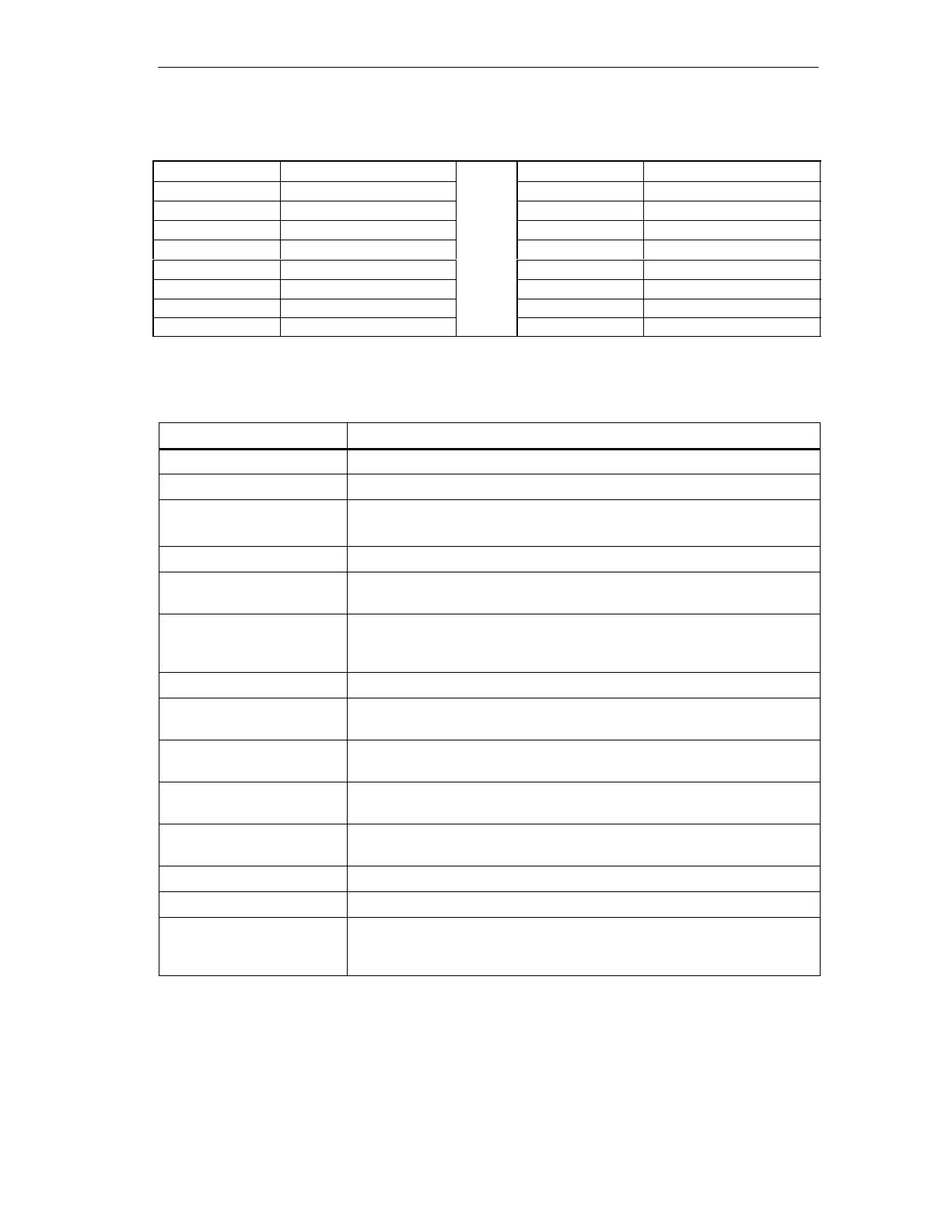
Flag 1 Flag 2
Bit Number Meaning Bit Number Meaning
0 OFFLINE_READY 0 OFFLINE
1 APF 1 INTERNAL
2 NORMAL_MODE 2 EEPROM_OK
3 CONFIG_MODE 3 AUTO_ADDR_ENABLE
4 AUTO_ADDR_AVAIL 4 PERIPHERY_FAULT
5 AUTO_ADDR_ASSI_GN 5 reserved
6 LDS_0 6 reserved
7 CONFIG_OK 7 MPO startup
Meaning of the Flags
Flag Meaning
OFFLINE_READY The flag is set when the offline phase is active.
APF This flag is set when the voltage on the AS-i cable is too low.
NORMAL_MODE This flag is set when the DP/AS-i Link 20E is in the normal mode.
(The flag is set when the CP is in the normal mode.)
CONFIG_MODE The flag is set in the configuration mode and reset in the protected mode.
AUTO_ADDR_AVAIL This flag is set when the automatic address programming can be executed
(in other words, exactly one AS-i slave is currently out of operation).
AUTO_ADDR_ASSIGN This flag is set when the automatic address programming is possible (in
other words, AUTO_ADDR_ENABLE = 1 and there is no “incorrect” slave
connected to the AS-i Interface).
LDS_0 This flag is set when an AS-i slave exists with address 0.
CONFIG_OK This flag is set when the desired (configured) and actual configuration
match.
OFFLINE This flag is set when the mode is to changed to OFFLINE or this mode has
already been adopted.
EEPROM_OK This flag is set when the test of the internal EEPROM did not detect any
errors.
AUTO_ADDR_ENABLE This flag indicates whether the automatic address programming is enabled
(BIT = 1) or disabled (BIT = 0) by the user.
INTERNAL This flag is always set.
PERIPHERY_FAULT This flag is set when at least one AS-i slave is signaling a peripheral fault.
MPO startup The “master_power_on_startup” flag is set after the power supply of the
AS-i slave master has been turned on. If the master is later
changed to OFFLINE, the bit is reset.

Table of Contents

Question and Answer IconNeed help?

Do you have a question about the Siemens DP/AS-Interface Link 20E and is the answer not in the manual?

Siemens DP/AS-Interface Link 20E Specifications

General IconGeneral
BrandSiemens
ModelDP/AS-Interface Link 20E
CategoryComputer Hardware
LanguageEnglish

Summary

Technical Description, Installation Instructions, Operation

General Notes on Operation – Safety Warnings

Essential safety precautions and guidelines for operating the DP/AS-i Link 20E module.

Installing the Module

Step-by-step instructions for mounting and installing the DP/AS-i Link 20E module on a standard rail.

Display and Control Elements

Explanation of the LEDs (ADR, BF, SF) and buttons (SET, DISPLAY) on the module's front panel.

Configuring the AS-Interface with the SET Button (Button Configuration)

Guide to commissioning the AS-Interface using the SET button for quick configuration.

Configuring the DP/AS-i Link 20E as a DP Slave on the DP Master

Process of setting up the DP/AS-i Link 20E as a DP slave on a PROFIBUS DP master.

Configuration in STEP 7 – Basic Configuration

Steps for basic configuration of the DP/AS-i Link 20E within STEP 7 HW Config.

Data Exchange Between the DP Master and AS-i Slave

Transferring AS-i Binary Values

Explains how to access binary inputs and outputs of AS-i slaves via the DP master in cyclic mode.

Addressing AS-i Slaves

Information on addressing AS-i slaves for input/output data mapping on the DP master.

Transferring AS-i Analog Values

Details on reading and writing analog values using acyclic PROFIBUS-DP V1 services.

Programming

Explanation of job parameters and data consistency for analog value transfer programming.

Using the Command Interface

Command Interface of the DP/AS-Interface Link 20E

How to control AS-i master responses from a user program via the command interface.

Description of the AS-i Slave Commands

Comprehensive reference for commands sent from DP master to DP/AS-i Link 20E for AS-i slave control.

Set_Permanent_Parameter

Command to configure a parameter value permanently stored in the DP/AS-i Link 20E EEPROM for an AS-i slave.

Write_Parameter

Command to pass a parameter value to an AS-i slave, stored temporarily in the DP/AS-i Link 20E.

Store_Actual_Parameters

Command to overwrite configured parameters with current actual parameters for all AS-i slaves.

Slave Diagnostics

Overview

General overview of slave diagnostics and error signaling to the DP master.

Station Status 1 to 3

Details on interpreting the diagnostic status bits for DP slave operation.

Structure of the Device-Related Diagnostic Information

Description of the structure for device-related diagnostic information.

Dealing with Problems/Error Displays

Replacing a Defective AS-i Slave/Automatic Address Programming

Guide to replacing failed AS-i slaves using the automatic address programming feature.

Error Displays/Remedying Errors

Lists common error causes and remedies for DP/AS-i Link 20E module operation.

Appendix A: AS-Interface Protocol Implementation Conformance Statement (PICS)

Part B Supported Slave Profiles

Lists supported AS-i slave profiles for analog slaves, detailing S7.3 and S7.4 integration.

How the AS-i cycle time depends on the number of connected slaves

Formula and explanation for calculating AS-i cycle time based on the number of connected slaves.

Appendix B: Structure of the PROFIBUS DP Parameter Assignment and Configuration Frame

Configuration Frame

Describes the structure of the configuration frame based on I/O operation requirements.

Structure of the Parameter Assignment Frame

Details the standard and user-specific parameter assignment frame structure.

Appendix C: References

Appendix D: Notes on the CE Mark

Area of Application

Details the product's compliance with noise emission and noise immunity requirements.

Appendix E: Glossary

E.1 Terms Relating to AS-Interface

Glossary of key terms and acronyms specific to the AS-Interface system.

E.2 Terms Relating to PROFIBUS

Glossary of essential terms and acronyms relevant to the PROFIBUS communication protocol.

Related product manuals