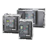
3.1.6.36 Controlled outgoing circuit for auxiliary equipment 400 V 3 AC or 460/480 V 3 AC (option
N33)
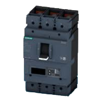
This option provides a controlled output that is protected via the motor circuit breaker and is
used for operating external auxiliary equipment (e.g. separately-driven fan for motor, pumps,
and oil supplies).
The contactor is energized by means of an ON command on the converter. The OFF command
deactivates the contactor.
Table 3-7 Outgoing circuit for auxiliary equipment (option N33)
Controlled outgoing circuit for auxiliary equipment Setting range of the motor circuit breaker
400 V 3 AC, 50 Hz, max. 15 KW Cos phi = 0.8; 28 A to 40 A
460/480 V 3 AC, 60 Hz, max. 17.5 KW Cos phi = 0.8; 28 A to 40 A
Table 3-8 T-X30 terminal strip for connecting auxiliary equipment
Supplying the auxiliary voltage Outgoing circuit for auxiliary equip‐
ment
Feedback: auxiliary equipment ON
Terminal Connector Terminal Connector Terminal Connector
.T–X30:6 L1 .T–X30:3 L1 .T–X30:1 Relay contact
max. 60 V DC
.T–X30:7 L2 .T–X30:4 L2 .T–X30:2
.T–X30:8 L3 .T–X30:5 L3
Note
The infeed required for the drive power supply must be provided externally.
3.1.6.37 Controlled outgoing circuit for auxiliary equipment 230 V 1 AC or 120 V 1 AC (option N35)
This option provides a controlled output that is protected via the motor circuit breaker and is
used for operating external auxiliary equipment (e.g. separately-driven fan for motor, pumps,
and oil supplies).
The contactor is energized by means of an ON command on the converter. The OFF command
deactivates the contactor.
Table 3-9 Outgoing circuit for auxiliary equipment (option N35)
Controlled outgoing circuit for auxiliary equipment Setting range of the motor circuit breaker
120 V 1 AC, 60 Hz, max. 1 KW
230 V 1 AC, 50 Hz, max. 1.2 KW
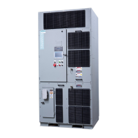
Description
3.1 Cabinet Details
SINAMICS PERFECT HARMONY GH180 6SR41 manufactured in NMA Nuernberg, Germany
54 Operating Instructions Rev.201706301306
 Loading...