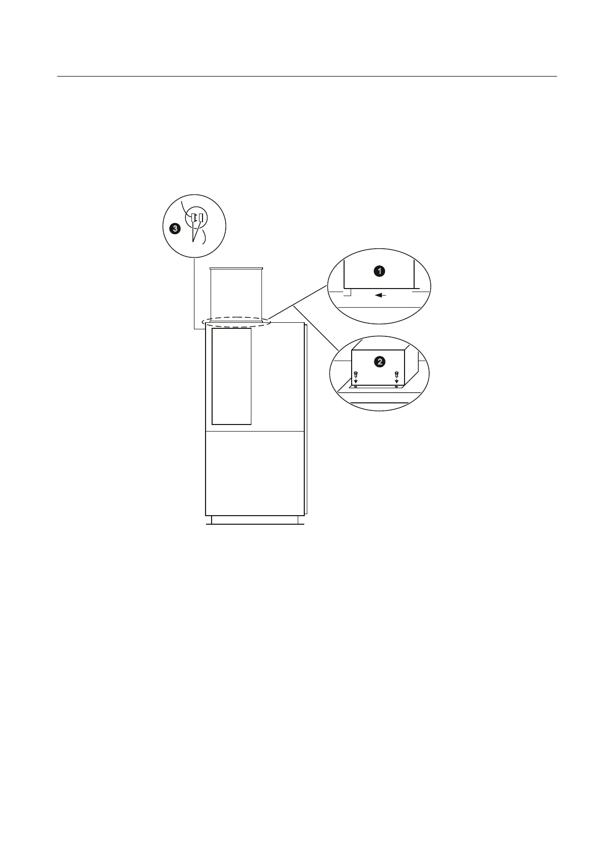
Procedure
1. Raise and place the fan housing on the power cell cabinet.
2. Tighten the screws (M6 x 25).
3. Connect the fans. The terminals (-X31 and / or -X32) for the power supply to the fans are
located at the top underneath the fans.
Figure 5-9 Schematic diagram for installing the fans (side view)
5.2.15 Installing the Fans (IP42)
Procedure
1. Raise and place the fan housing on the transport unit.
2. Tighten the screws of the fan housing (M6 x 16, M = 10 Nm).
Assembly
5.2 Assembly instructions
SINAMICS PERFECT HARMONY GH180 6SR41 manufactured in NMA Nuernberg, Germany
Operating Instructions Rev.201706301306 99
 Loading...