LOGO! manual
EWA 4NEB 712 6006-02
18
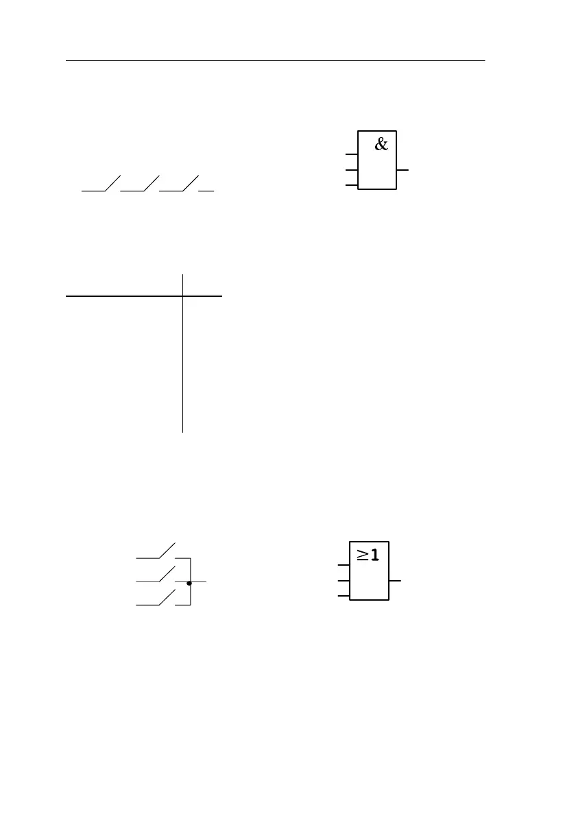
3.4.1 AND
I1
I2
I3
Q
The series connection of a number of
normally open contacts is represented
in a circuit diagram as follows:
The symbol for AND is as follows
The block is called AND because its output (Q) has the state 1 only when
I1 and I2 and I3 have the state 1 (i.e. they are closed).
Logic table for AND:
I1 I2 I3 Q
0 0 0 0
0010
0100
0110
1000
1010
1100
1111
3.4.2 OR
The symbol for this is as
follows:
I1
I2
I3
Q
The parallel connection of a number of
normally open contacts is represented in
a circuit diagram as follows:
The block is called OR because its output (Q) always has the state 1 when
I1 or I2 or I3 has the state 1 (i.e. closed). In other words, at least one input
must have the state 1.
Programming LOGO!
The following applies to AND: x = 1
(x means the input is not used)