31
LOGO! manual
EWA 4NEB 712 6006-02
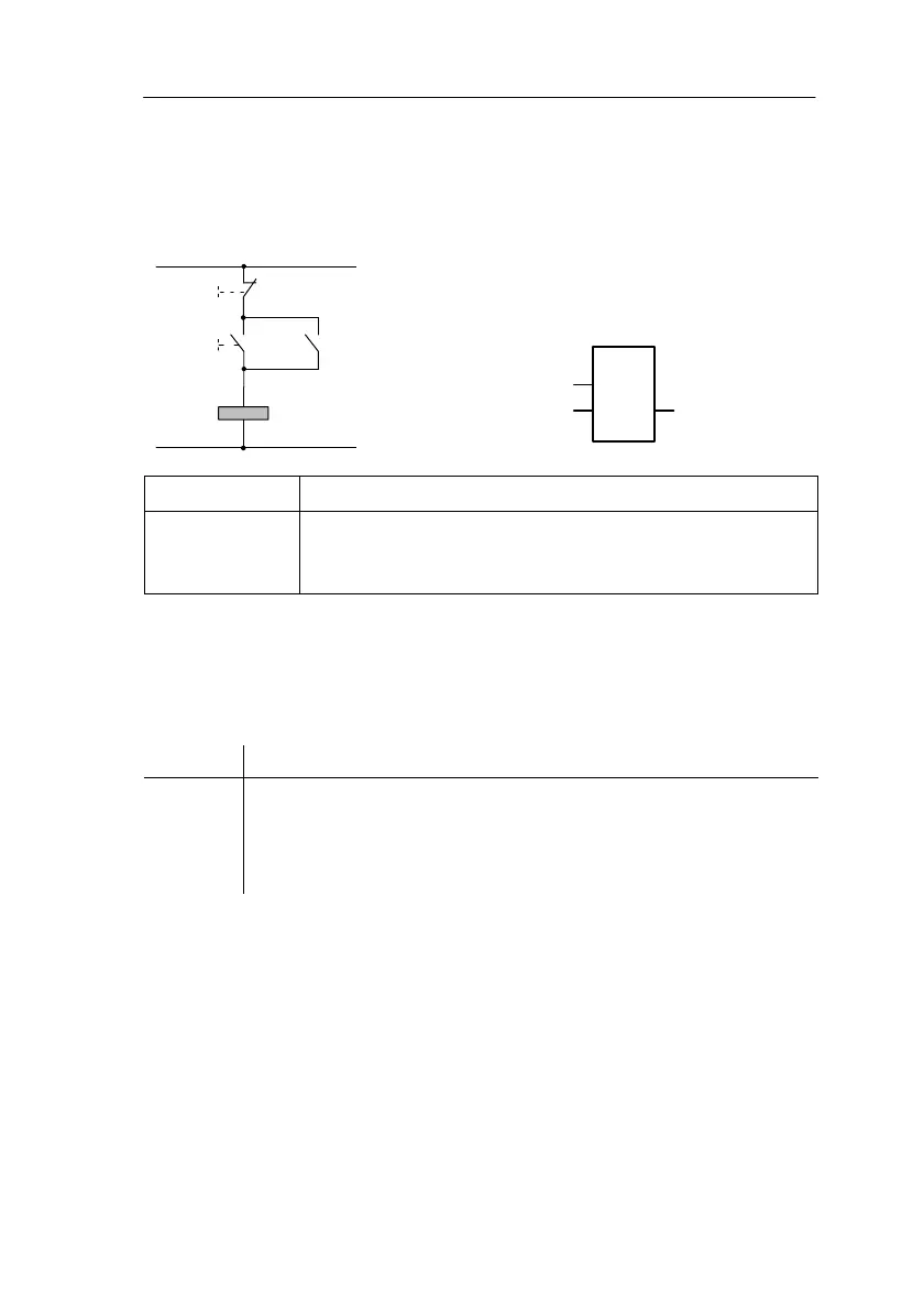
3.5.8 Latching relay
Very often, a circuit is required that retains a switched-on state. This is
referred to as latching. Latching is represented in a circuit diagram as fol-
lows:
LOGO! has a separate block for this type of cir-
cuit. The symbol for a latching relay is as fol-
lows:
S
RQ
RS
Q
Q
S
R
S input You set the output (Q) to 1 via the S input (Set).
R input You reset the output (Q) to 0 via the R input (Reset). If S and R
are both 1 at the same time, the output is reset (resetting takes
priority).
Switching behavior
A latching relay is a simple binary flip-flop. The value of the output de-
pends on the states of the inputs and the previous state of the output. The
following table illustrates the logic once more:
S
n
R
n
Q Note
0 0 Value remains the same
01 0Reset
10 1Set
11 0Reset (resetting has priority over setting)
Programming LOGO!
 Loading...

