87
LOGO! manual
EWA 4NEB 712 6006-02
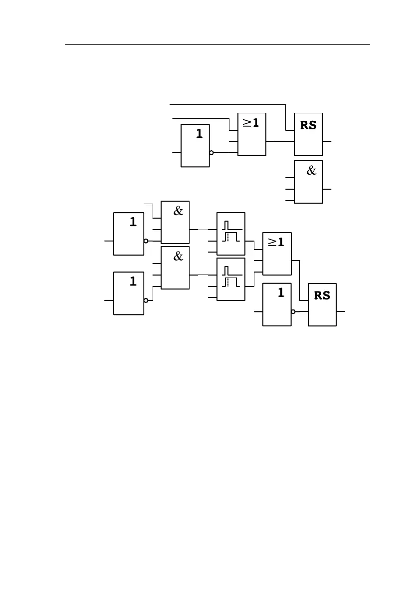
Block diagram of the LOGO! solution
The block diagram of the ventilation control system with LOGO! is as fol-
lows:
x
I1On
Q3Fault
I2Off
Q1
Exhaust
ventilator
Q2
Fresh air
ventilator
Q1
Exhaust
ventilator
I3
Exhaust air
flow monitor
x
I2Off
Fault
x
T=
10 s
x
T= 10 s
x
x
x
I3
Exhaust air flow
monitor
I4
Fresh air flow
monitor
Exhaust air ventilator Q1
Exhaust air ventilatorQ2
Q3
5.3.2 Advantages of using LOGO!
When you use LOGO!, you do not need as many switching devices. Thus,
you save on installation time and space in the switch box. You may even be
able to use a smaller switch box.
Additional options when using LOGO!
S The free output (Q4) can be used as a potential-free signalling contact in
the event of a fault or a power failure.
S It is possible to stagger the switching-off of the ventilators.
These functions can be implemented without additional switching devices.
Applications
 Loading...

