34 / 60
Siemens Actuators SAS.., SAT.. for valves CE1P4041en
Smart Infrastructure Functions and control 2019-04-09
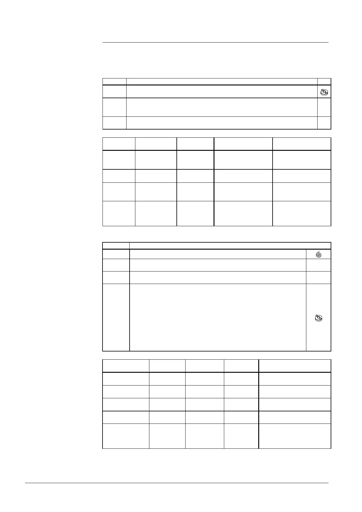
4.2.4 Signal priorities
The actuators are controlled via different interlinked positioning signal paths
(positioning signal “Y“, forced control input “Z“, manual adjuster). The signal paths
are assigned the following priorities (1 = highest priority, 4 = lowest priority):
Priority Description
1
The manual adjuster always has priority 1, thus overriding all signals active at “Z“ or
“Y“, independent of whether or not power is applied.
2
Only SA..61..: As soon as a valid positioning signal is active at input “Z“, the position
is determined via positioning signal “Z“ (forced control).
Prerequisite: The manual adjuster is not used.
Z
3
The position is determined via positioning signal “Y“ at Y, Y1 or Y2. The manual
adjuster is not used and on “Z“ there is no active signal.
Y
Manual
adjuster
Forced control
(Z)
Positioning
signal (Y)
Stroke actuator Rotary actuator
Automatic
mode
Not connected 5 V
Actuator’s stem travels
to position (50%)
Actuator’s spindle
travels to position
(50%)
Automatic
mode
G 3 V Actuator’s stem extends
Actuator’s spindle turns
in clockwise direction
Automatic
mode
G0 3 V Actuator’s stem retracts
Actuator’s spindle turns
in counterclockwise
direction
Operated
(30%) and
engaged
G 8 V
Actuator’s stem extends
manual (to 30%)
Actuator’s spindle turns
manually in
counterclockwise
direction (to 30%)
Bold printing = positioning signal currently active
Priority Description
1
The fail safe function responds in the event of a power failure.
2
The position is solely determined via positioning signal ”Z” (forced control),
provided power is applied.
Z
3
The position is determined by positioning signal Y, provided power is applied
and positioning signal ”Z” is not used.
Y
4
Upon actuation and slightly turning in counterclockwise direction, the manual
adjuster remains engaged.
Power applied:
After 5 seconds, the manual adjuster disengages itself and positioning signal
”Y” or ”Z” determines the position.
No power applied:
The actuator maintains the position defined by the manual adjuster until power
returns. Upon restoration of power, an automatic ClosedPosition-
Synchronisation will be performed.
Operating
voltage (G/G0)
Manual
adjuster
Forced
control (Z)
Positioning
signal (Y)
Stroke actuator
Applied
Automatic
mode
Not connected 5 V
Actuator’s stem travels to
position (50%)
Applied
Automatic
mode
G 3 V Actuator’s stem extends
Applied
Automatic
mode
G0 3 V Actuator’s stem retracts
Interrupted (fail
safe function)
Automatic
mode
G 6 V
Actuator’s stem retracts (until
end position is reached)
Interrupted (fail
safe function)
Operated
(30%)and
engaged
G 8 V
Actuator’s stem retracts (until
end position is reached), then:
Actuator’s stem extends
manually (to 30%)
Bold printing = positioning signal currently active
Actuator without
fail safe function
Examples
Actuator with fail safe
function
Examples

 Loading...