50 / 60
Siemens Actuators SAS.., SAT.. for valves CE1P4041en
Smart Infrastructure Connection diagrams and dimensions 2019-04-09
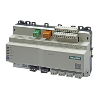
AC 230 V, 3-position
System neutral (SN)
Positioning signal (actuator’s stem extends)
Positioning signal (actuator’s stem retracts)
System potential (SP)
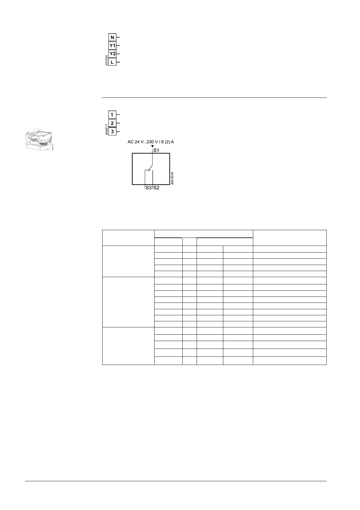
6.2.2 Electrical accessories
Adjustable switching points, AC 24…230 V
System potential (SP)
Closing (actuator’s stem extends)
Opening (actuator’s stem extends)
6.2.3 Cable labeling
The wires are color coded and labeled.
Connection
Cable
Description
Code No. Color Abbreviation
Actuators AC 230V N 4 blue BU System neutral
Y1 6 black BK Positioning signal
Y2 7 white WH Positioning signal
L - System potential
21 - Fail safe function
Actuators AC 24 V
resp. AC/DC 24 V
G 1 red RD System potential
G0 2 black BK System neutral
Y1 6 violet VT Positioning signal
Y2 7 orange OG Positioning signal
Y 8 grey GY Positioning signal
M - - Measuring neutral
U 9 pink PK Position feedback
Z - - Positioning signal forced control
AC/DC 24 V,
Modbus RTU
connection cable
G
1
red RD System potential
G0 2 black BK System neutral
REF 6 violet VT
Reference (Modbus RTU)
+ 8 grey GY
Bus + (Modbus RTU)
- 9 pink PK
Bus - (Modbus RTU)
SAT31.008
Auxiliary switch
ASC10.51

 Loading...