6.3 IAQ - CO2 connection diagrams (RDG2..KN)
For all applications and equipment combination supporting the IAQ -CO
2
function
(see IAQ - CO2 monitoring and control (RDG2..KN) [➙ 69]), the fresh air damper
(DC or On/Off) can be controlled via KNX S-Mode objects or directly connected to
the thermostat as follows:
● DC damper is connected to terminal U1
● ON/Off damper is connected to terminal Q3 (relay output).
Exception:
RDG204KN, for applications with 3-speed fan control: terminal Y4 (triac output)
6.4 Application examples
The examples are described for RDG26..KN, but they also apply to RDG20..KN.
Control output (P201, P204) and terminals for the valves (Y1, Y2) need to be
adapted accordingly.
6.4.1 Humidity control
In the following examples, P461 is configured based on the connected type of
equipment. See details in Humidity (RDG2..KN) [➙ 60].
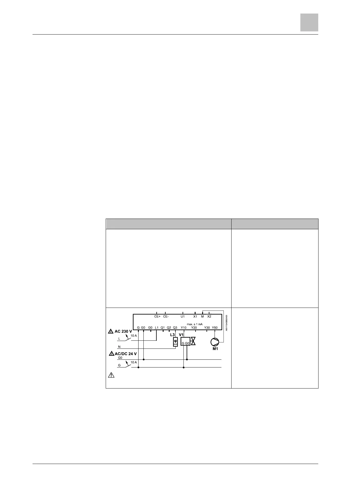
2-pipe fan coil application for dehumidification, with temperature setpoint shifting
and dehumidifier contact, DC 0...10 V fan and DC valve:
● Fan P351 = 3
(or DIP6 = OFF)
● Control strategy P450 = 1
● Setpoint high P024 = 50 %
(factory setting)
● Temp. shift P461 = 3 K
(factory setting)
● Valve P201 = 5
● Relay function P402 = 7
(dehumidifier)
 Loading...