Chapter 3
Communication Ports
RUGGEDCOM RX1500
Installation Guide
26 WAN Modules
• The modules have no user serviceable parts and equipment must only be repaired by authorized
Siemens personnel only.
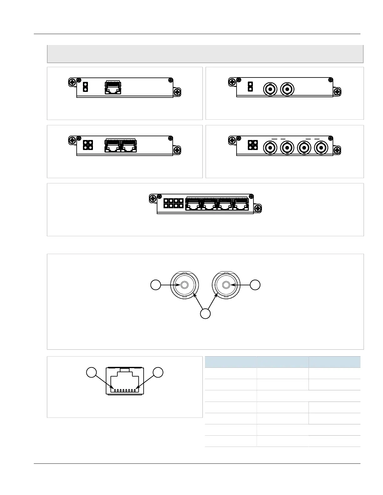
Figure 36: 1 × T1/E1 with RJ45 Ports (TC1)
Figure 37: 1 × E1 with BNC Ports (E01)
Figure 38: 2 × T1/E1 with RJ45 Ports (TC2)
Figure 39: 2 × E1 with BNC Ports (E02)
Figure 40: 4 × T1/E1 with RJ45 Ports (TC4)
The following is the pin-out for the BNC and RJ45 connectors:
Figure 41: RJ45 T1/E1 Pin Configuration
1. RTIP 2. TTIP 3. Chassis
Figure 42: RJ45C T1/E1 Pin Configuration
Pin Name Description
1 RRING Receive Negative
2 RTIP Receive Positive
3 Reserved (Do Not Connect)
4 TRING Transmit Negative
5 TTIP Transmit Positive
6 Reserved (Do Not Connect)
7 Reserved (Do Not Connect)
 Loading...