Description of the device
3.3 LED display
SCALANCE XR-500
Operating Instructions, 05/2017, A5E03275845-11
29
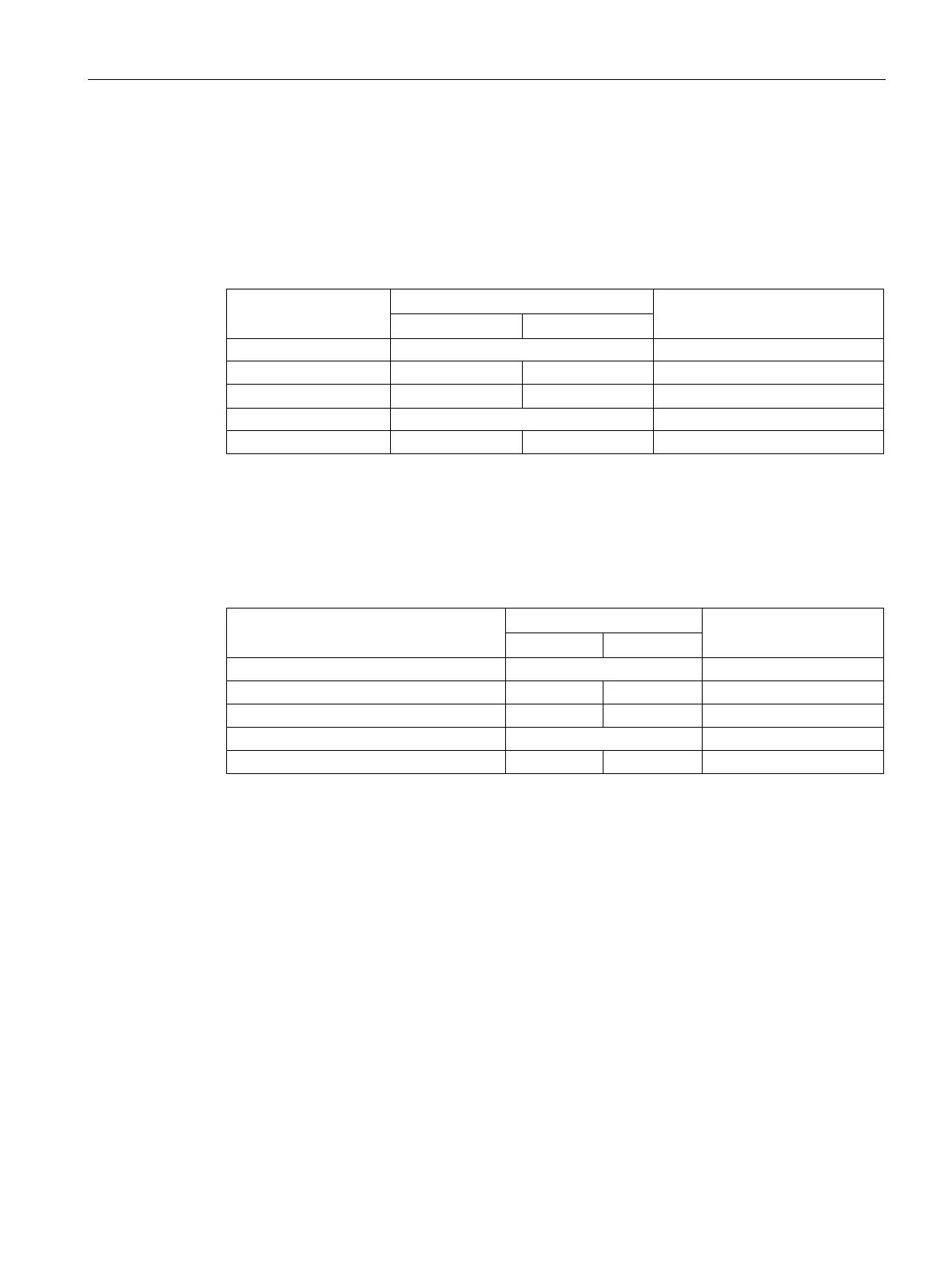
"DM1" and "DM2" LEDs for the display mode
The "DM1" and "DM2" LEDs indicate which display mode is set.
There are 5 display modes (A, B, C, D, and E). Display mode A is the default mode.
Depending on the set display mode, the "L1", "L2" LEDs and the port LEDs show different
information.
Green Off On Display mode C
To set the required display mode, press the "SELECT/SET" button.
If you do not press the "SELECT/SET" button for longer than 1 minute, the device
automatically changes to display mode A.
Pressing SELECT/SET button
starting at display mode A
"L1" and "L2" LEDs for the power supply
The "L1" and "L2" LEDs indicate the current range of the power supply at connectors L1 and
L2.
The meaning of the "L1" and "L2" LEDs depends on the set display mode, see section
""DM1" and "DM2" LEDs for the display mode (Page 29)".
For devices with 24 VDC, the voltage limit is 17 VDC.
With devices with 100 to 240 VAC, the voltage limit is 90 VAC.
 Loading...