Wiring
7.2 Terminal and block diagram
CPU 1515SP PC2 (F/T/TF)
Operating Instructions, 09/2018, A5E42603425-AA
37
Terminal and block diagram
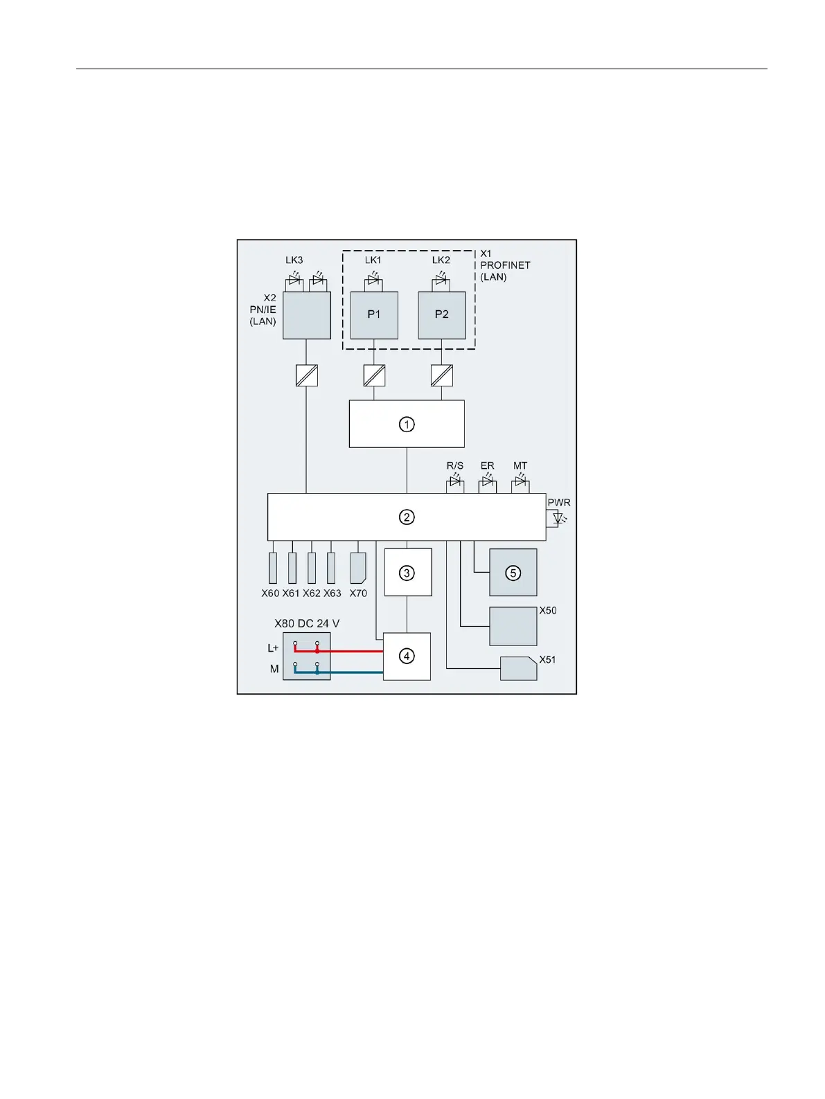
Block diagram
The following figure shows the block diagram for the CPU 1515SP PC2.
PROFINET interface X1 Port 1
PROFINET interface X1 Port 2
USB 3.0 interfaces, max. 0.9 A
RUN/STOP LED (yellow/green)
USB 2.0 interfaces, max. 0.5 A
Figure 7-1 Block diagram for the CPU 1515SP PC2

 Loading...