LEDs and connectors
2.3 Electrical connectors
CP 1243-1
Operating Instructions, 12/2016, C79000-G8976-C365-02
25
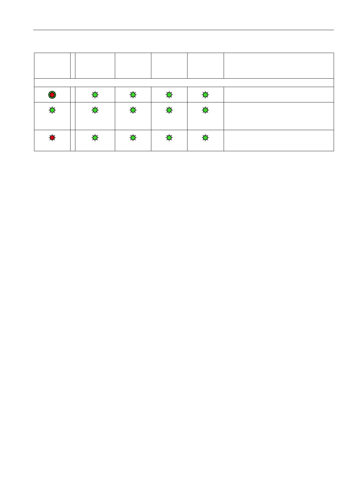
(red / green)
(green)
(green)
(green)
(green)
Meaning
(if more than one point listed: alternative
meaning)
Loading firmware. The DIAG LED flashes
alternating red and green.
flashing
Firmware was successfully loaded.
Error loading firmware
Electrical connectors
2.3.1
Power supply
Power supply
The CM is supplied with power from the backplane bus. It does not require a separate power
supply.
Ethernet interface X1P1
Ethernet interface
The Ethernet connector is located behind the lower hinged cover of the module. The
interface is an RJ-45 jack according to IEEE 802.3.
The pin assignment and other data relating to the Ethernet interface can be found in the
section Technical data (Page 101).

 Loading...


