Operation
5.2 DM-F PROFIsafe
36
SIMOCODE pro - Fail-Safe Digital Modules
Manual, 11/2017, NEB631679702000/RS-AA/002
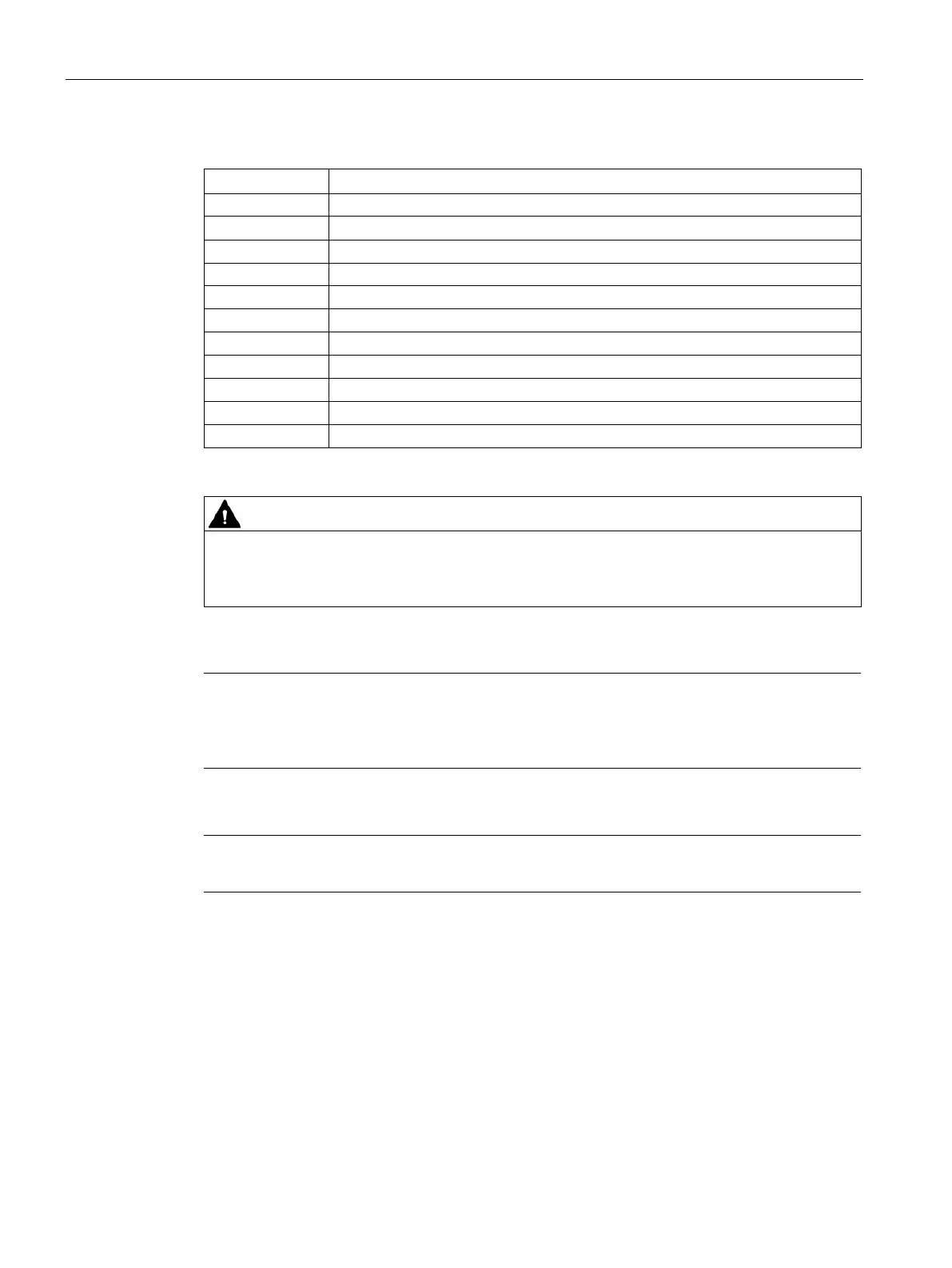
Table 5- 3 Terminal assignment of DM-F PROFIsafe
Digital module, relay outputs 1 (80) and 2 (86)
81, 87 Relay enabling circuit 1, NO
Relay enabling circuit 2, NO
83, 85, 89 Digital module, inputs 1, 2, 3
Supply for digital module, inputs 1 to 3, 24 V DC
Supply for feedback circuit 24 V DC
Power supply connection 110 to 240 V AC/DC or +24 V DC
Ground (reference potential for digital module inputs; 3UF7330-1AU00-0 only)
1)
Loss of safety function possible.
For the 24 V DC power supply, always use a power supply according to IEC 60536
protection class III (SELV or PELV).
1)
pro via terminal SPE with the maximum possible cross-section and
with as short a cable as possible to the functional ground of the control cabinet, e.g. to the
grounded mou
nting plate of the control cabinet.
Note
Surge suppressors are required for inductive loads.

 Loading...


