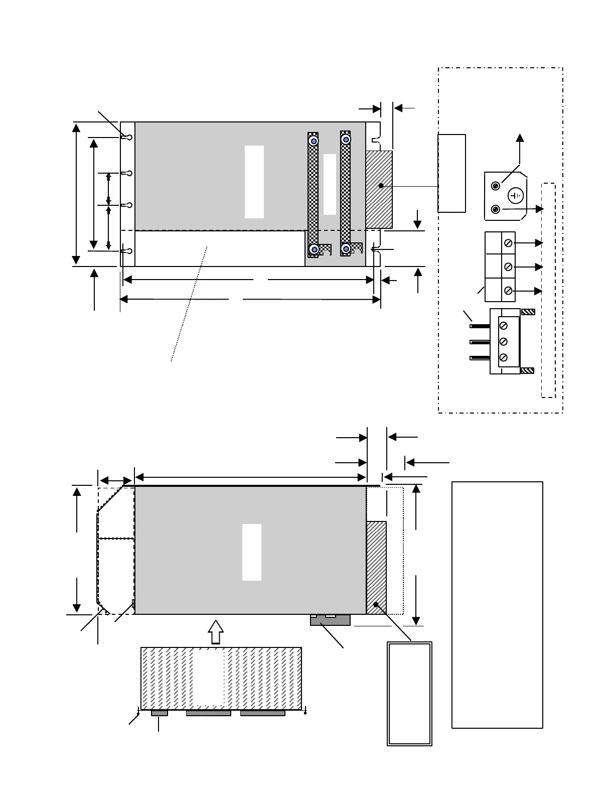
Front View
50mm(max.)
DC Link
8mm
Y
X
Z
a - 0.5mm
Module
5)
Side View
Controller
Board
1
2
4
100mm
Leave this area open for Air
443mm
Leave this area open for Air
Allow space for access
to connectors located
in this area.
3)
Power & Ground
Connections
To Motor Connections U V W
Ground
Earth
Ground
Star Point
U2 V2
W2 V2 U2
Styles, depending on
Module Size / Type
1) Board Retainer Screw - Tighten firmly
2) Connector - Supplied with PCB
3) Threaded Hole for alternate shield connecting point
(M5 x 8) [Encoder & Command Line Shield, etc.]
4) DC Link Cover
5) Clearance hole for M5 Screw(all mounting points)
6) Heat Shield for 10KW Power Infeed Module
NOTE
Siemens Energy and Automation, Inc.
Opening for
Controller Board
DIMENSION CHART ON FOLLOWING PAGE
 Loading...


