3
02.98
1-20
Siemens AG 1998 All Rights reserved 6SN1197–0AA00 02.98 Edition
SIMODRIVE 611 (PJ)
Function overview and settings
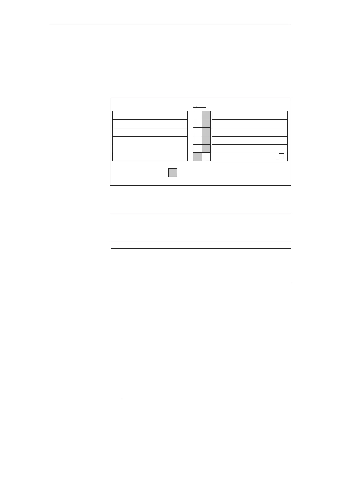
A switch S1 is provided on the upper side of the NE and monitoring module to
set the following functions (for UE5 KW on the front panel):
ON: OFF:
U
supply
=415V10% V
DC
link
=625 V
1)
Fault message
Regenerative feedback off
U
supply
=400V10% V
DC
link
600 V
1)
Regenerative feedback on
1
2
3
4
U
supply
=480V
+
6%–10%
Ready signal
S1
Controlled infeed off
Controlled infeed
5
6
Standard, refer to switch S1.1
Sinusoidal current operation
Square–wave current operation
Standard setting
Figure 3-1DIL switch S1
!
Important
For I/R modules, Order No. 6SN114–10–01 the basic setting is for
sinusoidal current operation.
!
Important
Terminal 63 (pulse enable) and/or terminal 48 (starting terminal, contactor con-
trol) must be de–energized or disconnected before the drive is powered–up or
down using the main circuit–breaker or line contactor!
OFF:I/R module, V
supply
=400V
10%; V
DC
link
=600V
UE module V
supply
=400V
10%; V
DC
link
=V
supply
1.35
Monitoring thresholds: (I/R, UE, monitoring modules)
Pulsed resistor on=644V; Pulsed resistor off=618V
V
DC
link
>>=695V
ON: I/R module V
supply
=415V
10%; V
DC
link
=625V
UE module V
supply
=415V
10%; V
DC
link
=V
supply
1.35
Monitoring thresholds: (I/R, UE, monitoring modules)
Pulsed resistor on=670V; Pulsed resistor off=640V
V
DC
link
>>=710V
PW=pulsed resistor
1)
only possible for the I/R module, monitoring thresholds are increased for all NE modules.
Switch S 1.1 :
3.1 Function overview and settings
 Loading...


