VS
07.94
1-96
Siemens AG 1997 All Rights reserved
SIMODRIVE 611A Installation and Start–Up Guide/IAA/–04.97 Edition
Speed controller optimization
The additional smoothing functions in the speed controller loop (damping me-
chanical resonance effects) are described in Section 3. Proceed as follows
when optimizing the speed controller:
4.Tachometer adjustment
5.Gain Kp
6.Integral action time T
N
7.Adaptation T
N
(if required)
8.I–component limiting (if required)
9.Drift compensation (offset)
The unit must be powered–up to optimize the speed controller
Therefore please refer to p. 1-121 ”Power–on”.
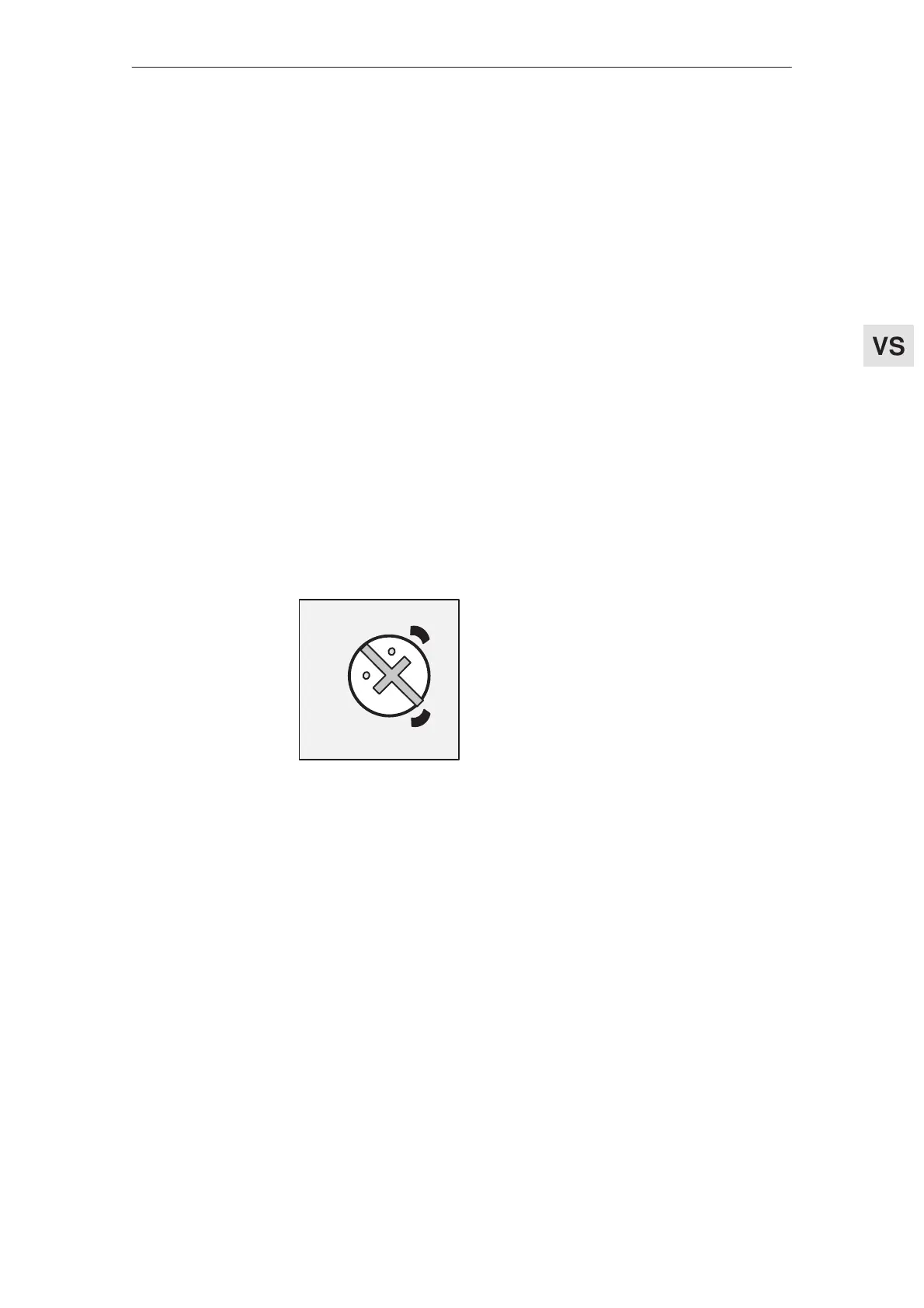
The potentiometer scale divisions (in the setting tables) are defined as follows:
8
9/
10
7
6
5
4
3
2
0/1
5
1
2
3
4
9
8
7
6
0
10
The setting shown in the diagram cor-
responds to 7 scale divisions.
Feed modules (VS)
2 Speed controller optimization
 Loading...


