Electrical connection
8.3 System integration
1FK2 synchronous motors for SINAMICS S120
104 Configuration Manual, 06/2019, A5E46927724B AB
Signal connection
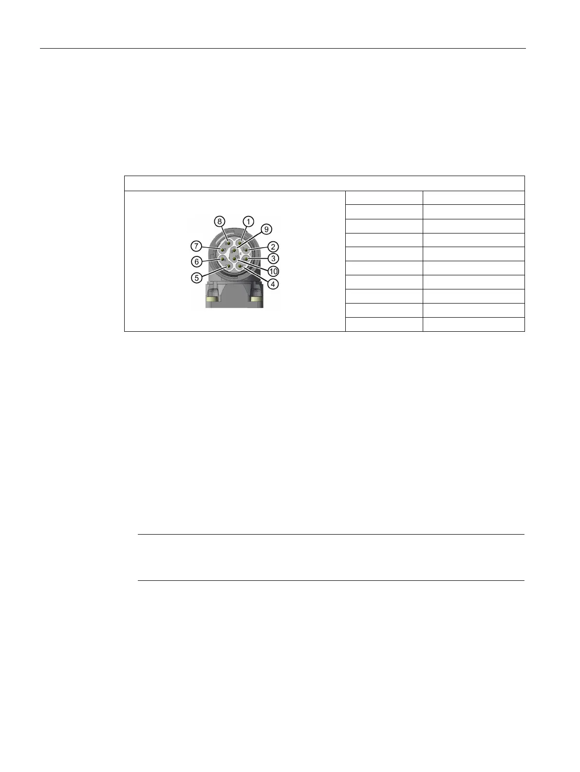
Design of the signal connector
The signal connector of the 1FK2 is an M17 round connector.
The connector pin assignment is as follows.
M17 signal connector, with DRIVE-CLiQ
2 TX-N
The signal connectors can be rotated within a certain range.
More precise information on the angle of rotation is available in Chapter "Rotating the
connector on the motor (Page 102)"
Connecting to a converter
8.3.4.1
Selecting and connecting the cables
● Use prefabricated MOTION-CONNECT cables from SIEMENS or shielded connecting
cables.
● The prefabricated MOTION-CONNECT cables reduce installation costs and increase the
operational reliability
Note
The cable shielding, made up of as many strands as possible, must have a high electrical
conductivity. Braided shields made of copper or aluminum are well suited.
When connecting, comply with the following:
● Connect the shield to the converter.
● Keep the unshielded cable ends as short as possible.
● To ensure good discharging of high-frequency currents, provide contacting over a large
surface area.

 Loading...


