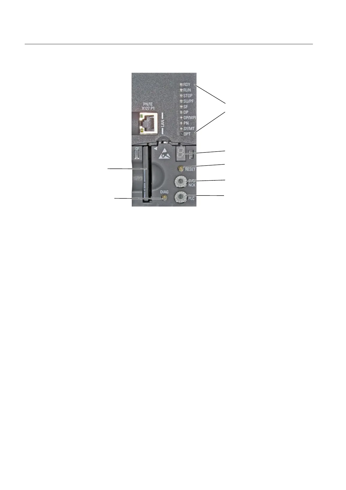
/('GLVSOD\V
&)FDUG
LQVHUWHGLQWKH
&)FDUGVORW
5HVHWEXWWRQ
6HUYLFHVHOHFWRUVZLWFK
0RGHVHOHFWRU
VHJPHQWGLVSOD\
'LDJQRVWLFVEXWWRQ
',$*
Figure 3-2 Control and display elements of the SIMOTION D4x5‑2
3.2
Operator controls
3.2.1 Service and operating mode switch
Characteristics of the Service switch and mode switch
SIMOTION D4x5‑2 has two selector switches on the lower front side for selection of the service
functions and operating modes.
The upper selector switch (labelled SVC/NCK) is for the selection of service and diagnostic
functions. In "normal" operation this switch must remain in the 0 position (see figure below).
The lower switch, labelled PLC, is used to set one or more operating modes of the
SIMOTION D4x5‑2.
Operator control (hardware)
3.2 Operator controls
SIMOTION D4x5-2
44 Manual, 04/2014
 Loading...


