Parameter Manual
Operating Instructions, 08/2013, 6FC5397-8EP40-0BA0
145
Machine data
2.3 Channel-specific machine data
Description: This machine data defines the speed regulation characteristic of the spindle
in G0 blocks with constant cutting rate (G96, G961) selected .
1: In a G0 block, the spindle speed is kept constant at the last value of
the previous block that was unequal G0.
Prior to a subsequent block that does not contain G0, the spindle speed is
increased to a value that belongs to the transverse axis position of the sub-
sequent block.
0: In a G0 block, the spindle speed changes against the transverse axis
position.
Description: Bit 0 = 1:
The M functions for subroutine end (M17 and/or M2/M30) are transferred to the
PLC interface.
Bit 0 = 0:
The M functions for subroutine end (M17 and/or M2/M30) are not transferred to
the PLC interface.
Note:
To prevent stopping in continuous-path mode, M17 must not be programmed alone
in a block.
Example of a subroutine: G64 F2000 G91 Y10 X10
X10 Z10 M17
Bit 1 = 0:
M01:
conditional program stop is always output to PLC, irrespective of whether the
M01 signal is active or not.
Fast auxiliary function output M=QU(1) is inactive because M01 is assigned to
the 1st M function group and thus is always output at block end.
Bit 1 = 1:
M01:
conditional program stop is only output to PLC, if M01 is also active.
This thus enables optimal run-time processing of the part program.
With fast auxiliary function output M=QU(1), M1 is output during the move-
ment; thus it is possible to traverse blocks in continuous-path mode with
programmed M01 as long as M01 is not active.
The request of the M01 signal with M=QU(1) no longer occurs at block end but
during the movement.
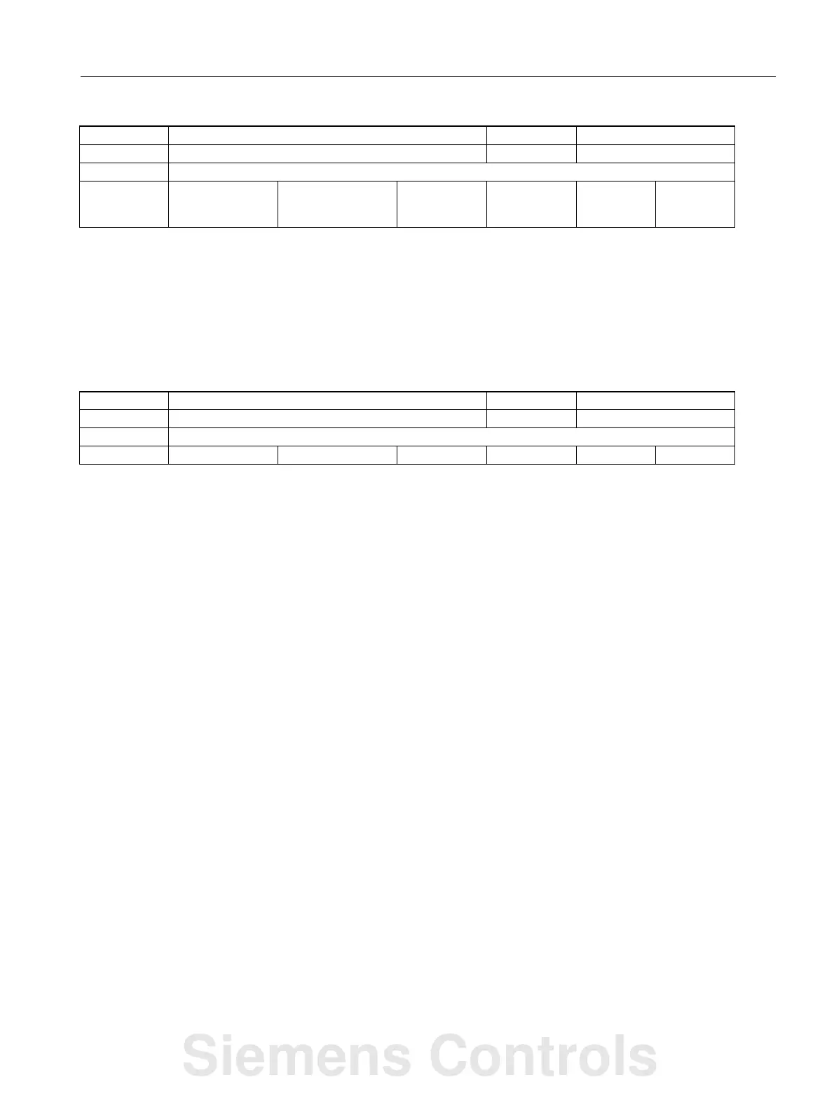
20750 ALLOW_G0_IN_G96 C09, C05 P2,V1
- G0 logic with G96, G961 BOOLEAN PowerOn
-
- - TRUE, TRUE, TRUE,
TRUE, TRUE, TRUE,
TRUE...
0 - 1/1
20800 SPF_END_TO_VDI C04, C03 H2,K1
- End of subroutine to PLC BYTE PowerOn
-
- - 1, 1, 1, 1, 1, 1, 1, 1... - - 1/1
Siemens Controls
 Loading...


