PLC User Interface
5.7 NCK signals
Parameter Manual
436
Operating Instructions, 08/2013, 6FC5397-8EP40-0BA0
5.6.6 Transferred D functions
5.6.7 Transferred H functions
5.7 NCK signals
5.7.1 General signals to NCK
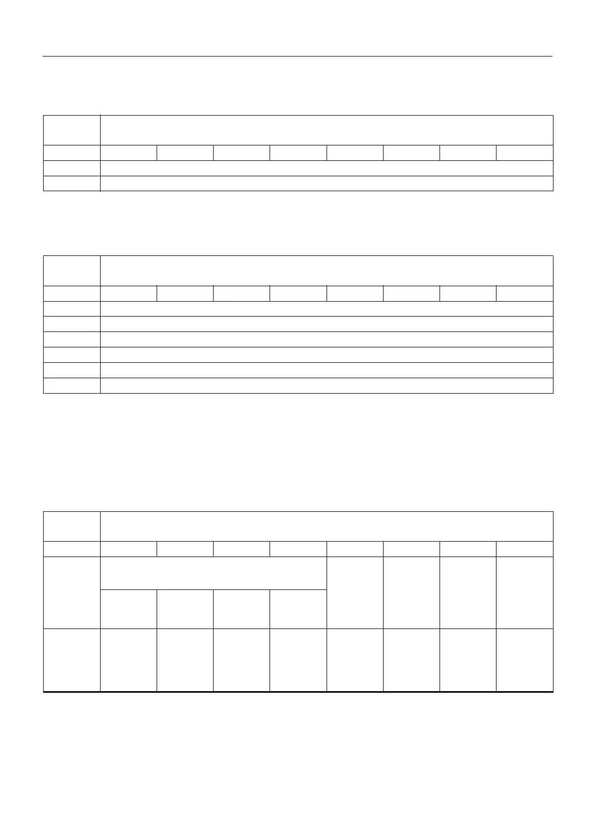
DB2500 D functions from NCK channel [r]
NCK -> PLC interface
Byte Bit 7 Bit 6 Bit 5 Bit 4 Bit 3 Bit 2 Bit 1 Bit 0
5000 D function 1 (DINT)
5004
DB2500 H functions from NCK channel [r]
NCK -> PLC interface
Byte Bit 7 Bit 6 Bit 5 Bit 4 Bit 3 Bit 2 Bit 1 Bit 0
6000 H function 1 (REAL) (DINT)
6004 Extended address H function 1 (byte)
6008 H function 2 (REAL)
6012 Extended address H function 2 (byte)
6016 H function 3 (REAL)
6020 Extended address H function 3 (byte)
DB2600 General signals to NCK [r/w]
PLC -> NCK interface
Byte Bit 7 Bit 6 Bit 5 Bit 4 Bit 3 Bit 2 Bit 1 Bit 0
0 Protection level
Keyswitch position 0 to 3
Acknowled
ge
EMERGEN
CY STOP
Acknowled
ge
EMERGEN
CY STOP
Braking
along the
contour in
case of
EMERGEN
CY STOP
4 567
1 Request
axis
distances to
go
Request
axis actual
values
INC inputs
in mode
signal
range
active
1)
1)
Refer to mode signals

 Loading...


