Parameter Manual
Operating Instructions, 08/2013, 6FC5397-8EP40-0BA0
321
NC setting data
Description: If this setting data is not equal to 0, the assignment of tool length compo-
nents (length, wear, base dimensions) to geometry axes is not changed when
the machining plane (G17 - G19) is changed.
The assignment of tool length components to geometry axes can be derived from
the value of the setting data acc. to the following tables.
A distinction is made between turning and grinding tools (tool types 400 to
599) and other tools (typically milling tools) in the assignment.
Representation of this information in tables assumes that geometry axes 1 to
3 are called X, Y and Z. For assignment of an offset to an axis, not the axis
identifier but the axis sequence is relevant.
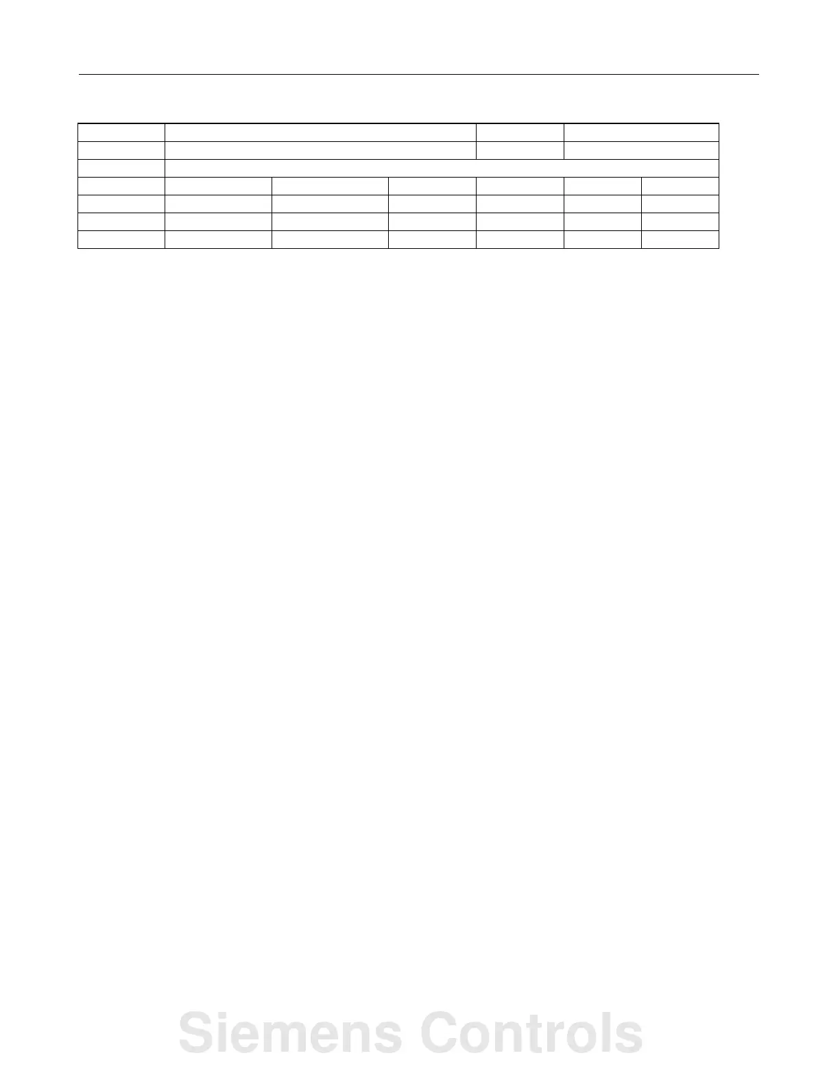
Assignment for turning tools and grinding tools (tool types 400 to 599):
Content Length 1 Length 2 Length 3
17 Y X Z
18* X Z Y
19 Z Y X
-17 X Y Z
-18 Z X Y
-19 Y Z X
* Any value which is not 0 and is not one of the six values listed, is
treated as value 18.
For values that are the same but with a different sign, assignment of length
3 is always the same, lengths 1 and 2 are reversed. Assignment for all tools
which are neither turning nor grinding tools (tool types < 400 or > 599):
Content Length 1 Length 2 Length 3
17* Z Y X
18 Y X Z
19 X Z Y
-17 Z X Y
-18 Y Z X
-19 X Y Z
* Any value which is not 0 and is not one of the six values listed, is
treated as value 17.
For values that are the same but with a different sign, assignment of length
1 is always the same, lengths 2 and 3 are reversed.
If the hundreds position of the settings data is 1, the sign of the second
length component is inverted.
If the thousands position of the setting data is 1, tool orientation and tool
normal vector are interpreted according to the content of the decade and unit
position. Otherwise, these two vectors are derived from the current G code of
group 6 (G17 - G19). This applies only, however, if the tool orientations
were not explicitly specified using tool parameters $TC_DPVx[i, j] or
$TC_DPVNx[i, j].
Example:
42940 TOOL_LENGTH_CONST -W1
- Change of tool length components with change of active plane DWORD Immediately
-
808d-me42 - 0, 0, 0, 0, 0, 0, 0, 0... - - 2/2
808d-me62 - 0, 0, 0, 0, 0, 0, 0, 0... - - 2/2
808d-te42 - 18 - - 2/2
808d-te62 - 18 - - 2/2
Siemens Controls

 Loading...


