Connecting
3.3 Connecting the interfaces on the PPU
Electrical Installation Manual
22 Operating Instructions, 12/2014, 6FC5397-2EP10-0BA0
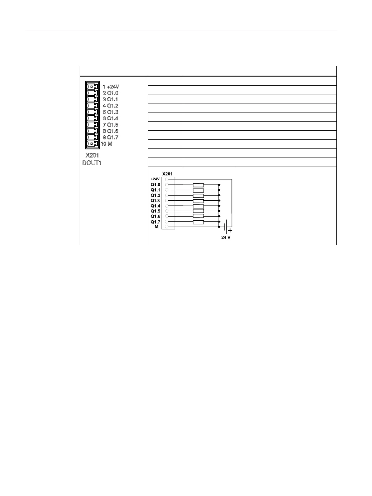
Table 3- 5 Pin assignment of X201 (DOUT1)
1 +24V +24V input (20.4 - 28.8 V)
2 Q1.0 Digital output
3 Q1.1 Digital output
4 Q1.2 Digital output
5 Q1.3 Digital output
6 Q1.4 Digital output
7 Q1.5 Digital output
8 Q1.6 Digital output
9 Q1.7 Digital output
10 M External ground
End sleeves are necessary if you use two cables per connection.
Fasten the cables to the screw terminals and plug the terminals into interfaces X200 and
X201 correctly.
Cable Shielded cable
Max. length: 10 m
Max. cross-section:
One cable per connection: ≥ 0.5mm2
Inputs Permissible level (including ripple)
High level: 18 V - 30 V
Low level: -3 V - +5 V

 Loading...


