Connecting
3.3 Connecting the interfaces on the PPU
Electrical Installation Manual
Operating Instructions, 12/2014, 6FC5397-2EP10-0BA0
29
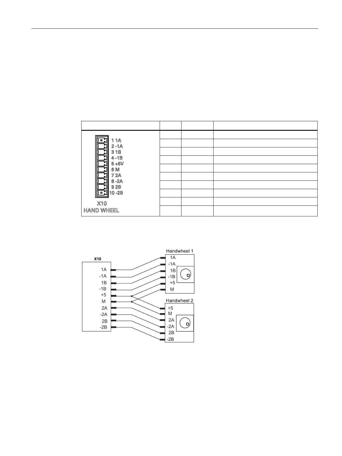
Handwheel inputs - X10
Pin assignment
Type Mini Combicon 10-pin
Cable Max. length: 3m
Table 3- 9 Pin assignment of X10
1 A1 TRACK A, handwheel 1
2 A1_N NEGATIVE TRACK A, handwheel 1
3 B1 TRACK B, handwheel 1
4 B1_N NEGATIVE TRACK B, handwheel 1
5 +5V +5V power output
6 M Ground
7 A2 TRACK A2, handwheel 2
8 A2_N NEGATIVE TRACK A2, handwheel 2
9 B2 TRACK B2, handwheel 2
10 B2_N NEGATIVE TRACK B2, handwheel 2
You are allowed to connect at most 2 electronic handwheels at connector X10 on the PPU.
The handwheels must meet the following requirements:
5V square wave signals (TTL level or RS422)
Signals Track A as a true and negative signal (U
a1
U
a1
)
Track B as a true and negative signal (U
a2
a2
Phase shift between Track A to Track
90
o
±30
o

 Loading...


