Connecting
7.2 Safety information for wiring
NCU 7x0.2
Manual, 02/2011, 6FC5397-0AP20-0BA0
47
Interface overview
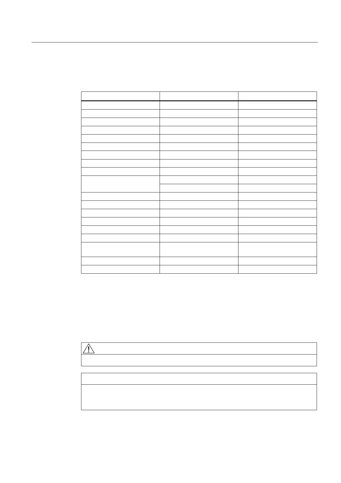
Table 7- 1 Overview of available external interfaces
Interface Designation Connector type
DRIVE-CLiQ (1) X100 Spec. RJ45 socket
DRIVE-CLiQ (2) X101 Spec. RJ45 socket
DRIVE-CLiQ (3) X102 Spec. RJ45 socket
DRIVE-CLiQ (4) X103 Spec. RJ45 socket
DRIVE-CLiQ (5) X104 (only NCU 720/730) Spec. RJ45 socket
DRIVE-CLiQ (6) X105 (only NCU 720/730) Spec. RJ45 socket
Ethernet IE1/OP X120 Standard RJ45 socket
Ethernet IE2/NET X130 Standard RJ45 socket
Ethernet (service socket) X127 Standard RJ45 socket
Port 1 (only "PN NCUs") Standard RJ45 socket PROFINET
Port 2 (only "PN NCUs") Standard RJ45 socket
Digital inputs/outputs X122, X132 Screw terminals, 2x12-pin
24 V power supply X124 Screw terminals, 4-pin
USB interfaces X125, X135 USB socket
PROFIBUS DP1 X126 9-pin SUB-D socket
PROFIBUS DP2/MPI X136 9-pin SUB-D socket
RS232 X140 9-pin SUB D plug connector
Measuring sockets (T0, T1, T2,
and G)
X131 - X134 Sockets on the printed-circuit
board
CompactFlash Card X109 50-pin socket
Dual fan/battery module X190 6-pin
7.2 Safety information for wiring
Note the following:
Safety information
DANGER
The system power supply must be disconnected when you wire the control unit.
NOTICE
If your axis grouping contains a Smart Line Module without DRIVE-CliQ (5 kW or 10 kW),
you must assign the Smart Line Module enable signal to digital output X122.1 on the
control unit.
 Loading...


