Connecting
7.9 Digital inputs/outputs
NCU 7x0.2
76 Manual, 02/2011, 6FC5397-0AP20-0BA0
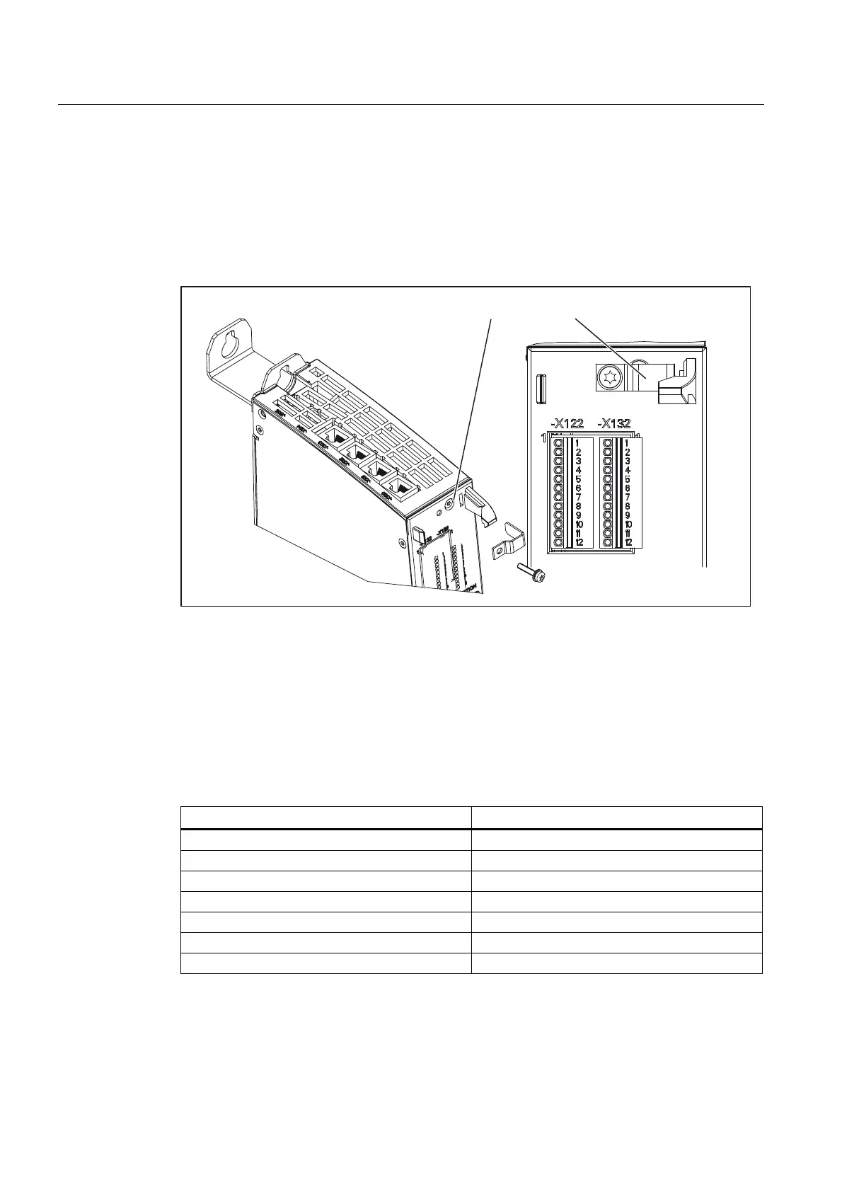
Using a shield connection
1. Remove the fixing bracket.
2. Insert the cable and fasten the fixing bracket.
This figure shows where to attach the cables to the front panel connector and where to apply
the cable interference suppression using the shield connecting element.
6KLHOGVXSSRUW
Figure 7-15 Using a shield connection
7.9.3 Technical data
Digital inputs on X122/X132
Table 7- 25 Technical data of digital inputs X122/X132
Parameters Values
Voltage -3 V to 30 V
Typical power consumption 10 mA at 24 V DC
Galvanic isolation Reference potential is terminal G1 or G2
Signal level (including ripple) High signal level: 15 V to 30 V
Low signal level: -3 V to 5 V
Signal propagation delays L → H: 50 μs
H → L: 100 μs
 Loading...


