Connecting
7.9 Digital inputs/outputs
NCU 7x0.2
Manual, 02/2011, 6FC5397-0AP20-0BA0
75
7.9.2 Connecting digital inputs/outputs
Cable specification
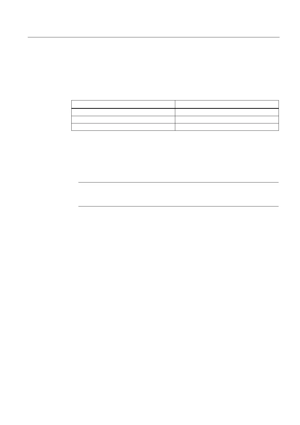
Table 7- 24 Cable specification for X122 and X132
Characteristics Version
Connector type Screw-type terminals
Connection option Up to 0.5 mm
2
Current carrying capacity 4 A max.
Connecting cables for digital inputs/outputs
The following conditions apply to connecting cables:
● Use flexible cables with a cable cross-section of at least 0.25 mm
2
● Ferrules are not required.
Note
To achieve optimum interference suppression, shielded cables must be used to connect
measuring inputs or BEROs.
Tools required
3.5-mm screwdriver or power screwdriver
Wiring digital inputs/outputs
1. Strip 6 mm of insulation from the wires.
2. Wire the digital inputs of the interface for connection of the sensors.
3. Wire the digital outputs of the interface for connection of the actuators.
4. Insert the cable into the corresponding spring-loaded terminal.
Using shielded cables
The following options are available for the shield connection when using shielded cables:
1. Attach the cable shield to a grounded shielding bus immediately after the cable entry
point in the cabinet (strip the insulation off the cable for this purpose).
2. Continue routing the shielded cable as far as the module but do not make a connection to
the shield there.
 Loading...


