Operating Instructions SIPLUS CMS4000 IFN AI-D
SIPLUS CMS4000 IFN AI-D
Operating Instructions, 07/2021, A5E32612781A-AB
21
4.2.5 Analog Input Channel
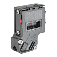
Connect the sensors / process signals to the 5-pin circular plug M12 (CH1-CH6) on the
front side of the device.
Chart 7 Channel 1-6, see chapter 6.2
Analog Input 1
CH2 Analog Input 2
Analog Input 3
CH4 Analog Input 4
Analog Input 5
CH6 Analog Input 6
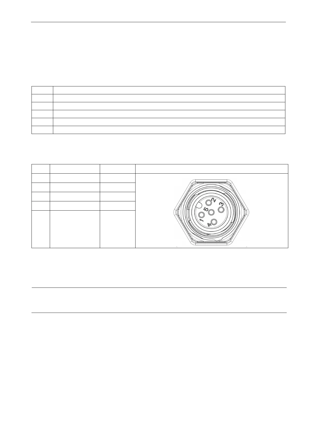
Connector assignment analog input (CH1-CH6)
Chart 8 Connector assignment analog input (CH1-CH6)
PIN Assignment Wire color Display
1 M (earth) brown
2 free white
3 Signal blue
4 free black
5 free
grey or
green/yellow
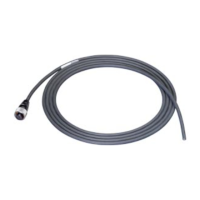
Shielding measurement CH1-CH6
Caution
Use only shielded lines, where the shielding is applied to one side of the IFN AI-D plug housing!
 Loading...