Description, device design, dimension drawing
2.5 Operating mode
SITOP PSU6200 1ph
Manual, 03.2019, A5E44623264-1-76
15
2.5 Operating mode
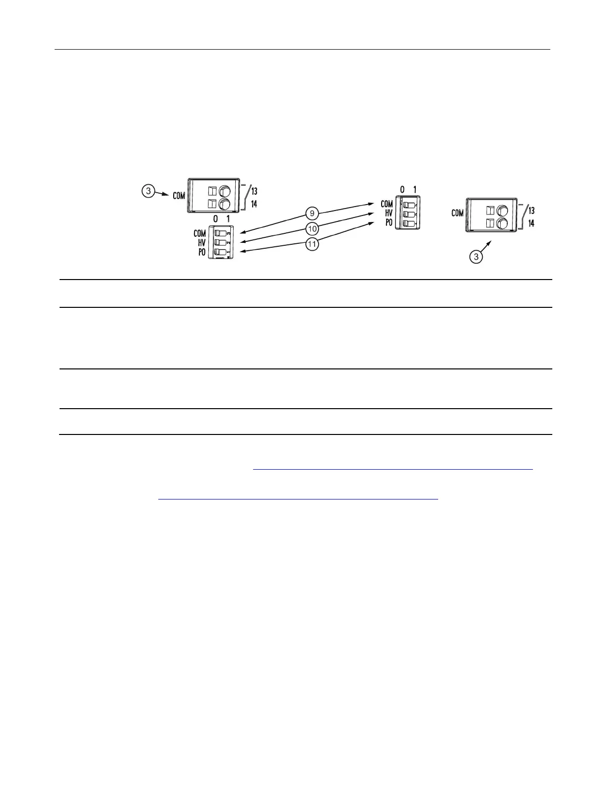
The selection is made using individual DIP switches (when supplied, these are in the 0
position).
It is only permissible to connect two identical devices in parallel to increase the power by
changing over the output characteristic by switching selector switch PO
⑪ to 1
6EP3324-7SB00-3AX0 (12 V/12 A)
6EP3334-7SB00-3AX0 (24 V/10 A)
6EP3336-7SB00-3AX0 (24 V/20 A)
Selector switch to toggle between the U
out
status display and the communication
0: Display of the output voltage status
1: Internal device parameters are transferred via signaling contact (13, 14) (diagnostics interface)
It is not permissible that the signaling contact is connected on the primary side!
Contact rating: 24 V AC/0.1 A; 30 V DC/0.1 A
Setting, above which value, the "O.K." LED is lit.
0: > 10 V
Setting, above which the "O.K." LED is lit
0: > 20 V
1: > 23 V
Switching over output characteristic 0: Constant output voltage "single operation" 1: Load-de-
pendent output voltage "parallel operation"
Additional information can be found in the documents:
● Diagnostics interface (https://support.industry.siemens.com/cs/ww/en/view/109763467)
● Faceplates and communication blocks
(https://support.industry.siemens.com/cs/ww/en/view/109760217
)

 Loading...