10
TUTORBIT
COSMOGAS
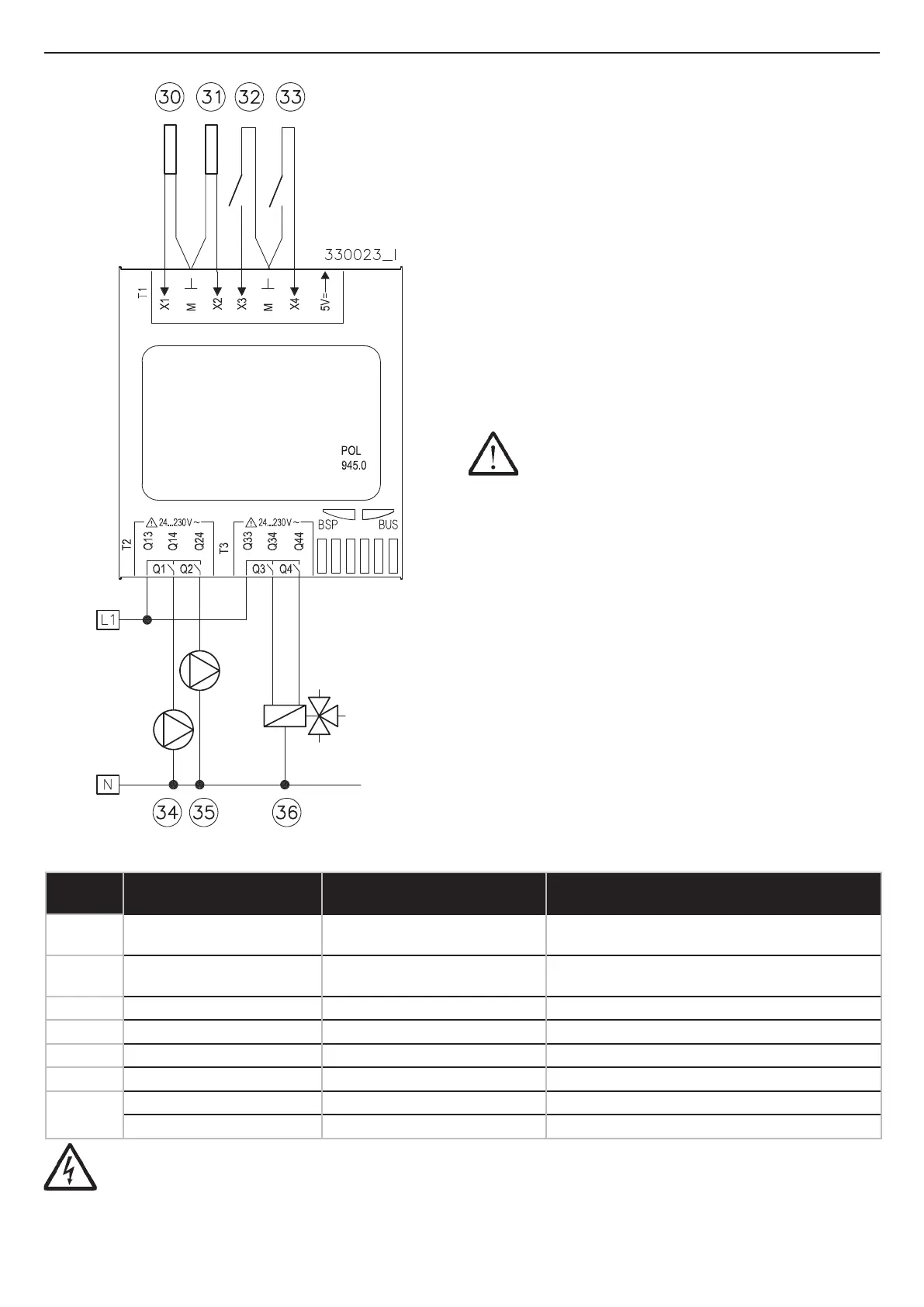
Figure 4-3 - Electrical connections POL945
4 - INSTALLATION
Legend
Input/output description Corresponding terminals on
expansion POL945
Characteristics of the cables to be used
and maximum electrical absorption
30
Solar tank sensor
(NTC 10kohm B3435)
X1; M (1) Ø 1,5 mm
2
/ 20 m Max o 100 m shielded cable;
31
Supply sensor “n”
(NTC 10kohm B3435)
X2; M (1) Ø 1,5 mm
2
/ 20 m Max o 100 m shielded cable;
32 Circuit “n” RT X3; M (1) Ø 1,5 mm
2
/ 20 m Max o 100 m shielded cable;
33 Anti-legionella Forcing X4; M (1) Ø 1,5 mm
2
/ 20 m Max o 100 m shielded cable;
34 Shue pump Q13; Q14 Ø 2,5 mm
2
/ 50 m Max / 3A Max;
35 Zone “n” pump Q13; Q24 Ø 2,5 mm
2
/ 50 m Max / 3A Max;
36
3 way valve zone “n” open Q33; Q34 Ø 2,5 mm
2
/ 50 m Max / 3A Max;
3 way valve zone “n” close Q33; Q44 Ø 2,5 mm
2
/ 50 m Max / 3A Max;
4.2 - Electrical connections
of POL 945 expansion
The POL 945 expansion can be used for dierent purposes,
depending on the logical address that is set (see Section 4.4).
When the logical address “1” is set, the POL 945 expansion
can control:
a.- An heating zone;
b.- A solar zone;
c.- The start of the anti-legionella cycle from an external
input;
d.- The shue pump for multiple tanks or for anti-legionella
with solar.
If the POL 945 expansion is used with logical address “2”, “3”
or “4” (see Section 4.4), it can only control one heating zone
(see diagrams in Section 4.21).
The POL 945 expansion can be installed on a DIN rail and is
supplied with the terminals for the electrical connections and
the bayonet for the electrical connection to TutorBit.
ATTENTION!!! The “Solar tank sensor” (30), “Anti-
legionella forcing” (33) and “Shue pump” (34) devices
of the table in Figure 4-3 can only be connected to the
expansion “POL 945 (Circuit 3)” ( see Figure 4-5).
ATTENTION !!! The terminals marked with (1), being subjected to very low safety voltage (24Vdc), must ow
in conduits other than 230Vac power supplies.
 Loading...