EasyManua.ls Logo

Siemens Vector Control User Manual

Siemens Vector Control
438 pages
Go to English
To Next Page IconTo Next Page
To Previous Page IconTo Previous Page
Page #264 background image
Connecting-up 05.2006
6SE7087-2JD60 Siemens AG
7-20 Operating Instructions SIMOVERT MASTERDRIVES
7.3 Fan fuses (only type D)
Line voltage 3 AC 200 V to 230 V
Order No.
6SE70..
Fan Fuse
(F101 / F102)
25-4CD60
25-4CD60-1AA1
FNQ-R-2
27-0CD60
27-0CD60-1AA1
FNQ-R-2
28-1CD60
28-1CD60-1AA1
FNQ-R-2
Manufacturer: FNQ-R Bussmann
Line voltage 3 AC 380 V to 480 V
Order No.
6SE70..
Fan Fuse
(F101 / F102)
23-8ED61
23-8ED61-1AA1
FNQ-R-6/10
24-7ED61
24-7ED61-1AA1
FNQ-R-6/10
26-0ED61
26-0ED61-1AA1
FNQ-R-6/10
27-2ED61
27-2ED61-1AA1
FNQ-R-6/10
Manufacturer: FNQ-R Bussmann
Line voltage 3 AC 500 V to 600 V
Order No.
6SE70..
Fan Fuse
(F101 / F102)
23-0FD61
23-0FD61-1AA1
FNQ-R-6/10
23-4FD61
23-4FD61-1AA1
FNQ-R-6/10
24-7FD61
24-7FD61-1AA1
FNQ-R-6/10
Manufacturer: FNQ-R Bussmann

Table of Contents

Question and Answer IconNeed help?

Do you have a question about the Siemens Vector Control and is the answer not in the manual?
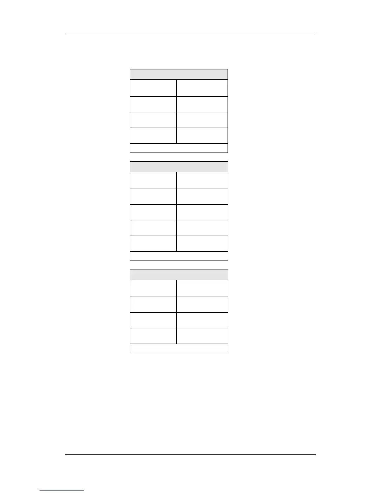
Siemens Vector Control Specifications

General IconGeneral
BrandSiemens
ModelVector Control
CategoryMedia Converter
LanguageEnglish

Summary

Operating Instructions

SIMOVERT MASTERDRIVES Product Overview

Overview of the SIMOVERT MASTERDRIVES frequency converter and its capabilities.

Definitions and Warnings

Qualified Personnel and Safety Alerts

Details on qualified personnel and hazardous situation warning categories (DANGER, WARNING, CAUTION, NOTICE).

Safety and Operating Instructions Scope

General safety guidelines for drive converters and adherence to directives.

First Start-up Procedure

Initial Setup and Connection Steps

Steps for unpacking, checking unit integrity, and connecting power and control cables.

Installation Guidelines

Installing the Units

Procedures for mounting units, including clearances and environmental requirements.

EMC Compliant Installation

Basic EMC Rules

Fundamental rules for electrical installation to ensure electromagnetic compatibility (EMC).

Connecting the Drive Converter

Power Connections

Guidelines for connecting protective conductors and power cables, including cross-sections and fuse recommendations.

Parameterization

Parameter Menu Structure and Navigation

Overview of parameter menus, levels, and main menu selection via P060.

Parameter Input Methods

Methods for parameter input including DriveMonitor, PMU, OP1S, and script files.

Parameterizing Steps

Parameter Reset and Quick Procedures

Procedures for resetting parameters to factory settings and performing quick parameterization.

Control Word and Status Word

Control Word Bit Descriptions

Detailed explanation of the function and meaning of each bit in the control word.

Status Word Bit Descriptions

Explanation of the meaning and significance of each bit in the status word.

Maintenance Procedures

Forming DC Link Capacitors

Faults and Alarms

Fatal Errors (FF)

List of serious hardware or software errors (FF) and their respective counter-measures.

Alarms List

Related product manuals