User Manual of A90 Series Inverter
268
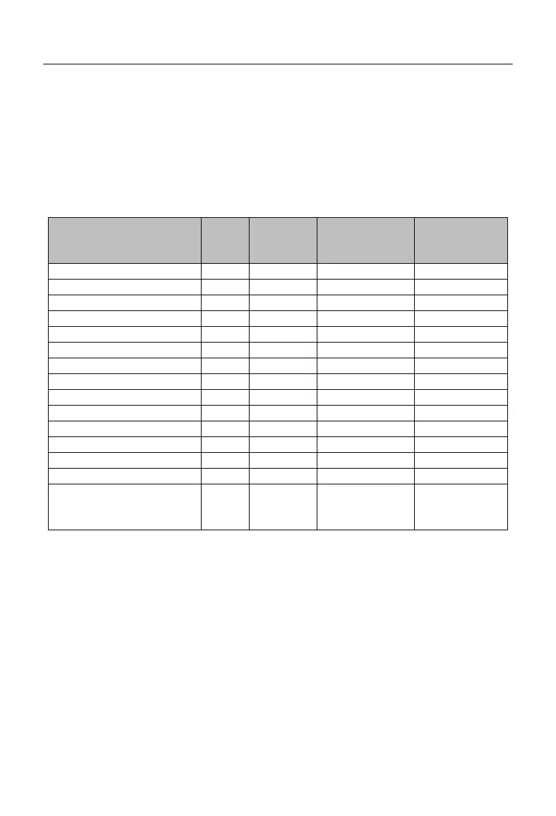
The recommended power and resistance for the braking resistor of the A90 series
inverter are given in the table below. The recommended resistor power is calculated based
on the braking rate (10% to 20%). It is for reference only. If the inverter is used in the case
of frequent acceleration/deceleration or continuous braking, the power of the braking
resistor needs to be increased. The user can change the value according to the load
conditions, but within the specified range.
Wire (mm
2
)
Connected to
Resistor
Wire (mm
2
)
Connected to
Resistor
★
The wires listed above refer to the outgoing wires of a single resistor. If resistors
are connected in parallel, the bus should be enlarged accordingly. The withstand
voltage of the wires should be AC300V or above for the single-phase model and
AC450V or above for the three-phase model. Cables should be resistant to
105°C .
11.2 Braking Unit
For the A90 series inverters (A90-4T60 and above), use our BR100 series braking
units (power range: 18.5-160kW). The models of our braking units are as follows.
 Loading...