User Manual of A90 Series Inverter
37
3.2.7
Ground wire
The ground terminal must be grounded.
Pay special attention to the third type of grounding (grounding resistance: less
than 10Ω).
The ground wire must not be shared by the welding machine and power
devices.
Select the ground wire according to the technical specifications for electrical
equipment, and minimize the length of the ground wire connected to the
grounding point.
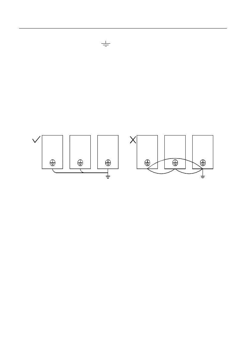
Where two or more inverters are used, the ground wires must not form a loop.
The correct and incorrect grounding methods are shown in Fig. 3-10.
Inverter Inverter InverterInverterInverterInverter
Fig. 3-10 Connection of Ground Wire
3.2.8
Installation and wiring of braking resistor and braking unit
Refer to 0 for the selection and wiring of the braking resistor and braking unit.
For the inverter with a built-in braking unit, connect the braking resistor between the
inverter terminal (+) and PB terminal. For the inverter with no built-in braking unit, connect
the terminals (+ and -) of the braking unit to those (+ and -) of the DC bus of the inverter,
and the braking resistor to the PB+ and PB- terminals of the braking unit. Refer to the user
manual of the BR100 braking unit for more information.
3.3 Wiring of Control Circuit Terminal
 Loading...