User Manual of A90 Series Inverter
28
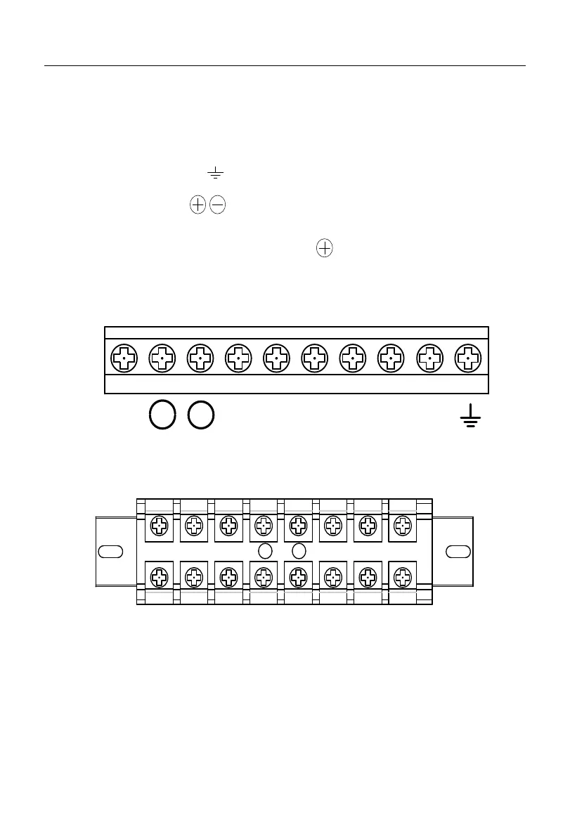
3.2 Wiring of Main Circuit Terminal
3.2.1
Composition of main circuit terminal
The main circuit terminal of the A90 series inverter consists of the following parts:
Three-phase AC power input terminals: R, S, T
Earth terminal:
DC bus terminals:
Terminals of dynamic braking resistor: PB,
Motor terminals: U, V, W
The layout of main circuit terminals is shown in Fig, 3-2.
a)
Schematic Diagram of Small- and Medium-power Main Circuit Terminals
Some power values vary slightly.
b)
Schematic Diagram of High-power Main Circuit Terminals (with slight variations in
some power values)
Fig. 3-2 Schematic Diagram of Main Circuit Terminal Layout
 Loading...