User Manual of A90 Series Inverter
29
3.2.2
Functions of main circuit terminals
The functions of the main circuit terminals of the A90 series inverter are shown in
Table 3-1. Please connect wires correctly according to the corresponding functions.
Table 3-1 Functions of Main Circuit Terminals
AC power input terminal, connected to three-phase AC power
supply
AC output terminal of the inverter, connected to three-phase
AC motor
Positive and negative terminals of the internal DC bus,
connected to external braking unit
Braking resistor terminal, with one end of the braking resistor
connected to and the other end to PB
DC reactor terminal, for the external DC reactor of A90-4T176
and above
Grounding terminal, connected to earth
3.2.3
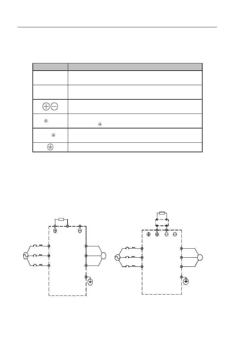
Standard wiring diagram of main circuit
The standard wiring diagram of the main circuit of the A90 series inverter is shown in
Fig. 3-3.
A90-4T1R5B to A90-4T045B
S
R
M
Braking resistor
(optional)
PB
U
V
WT
M
Braking resistor (optional)
Braking unit (optional)
R
S
TW
V
U
Fig. 3-3 Standard Wiring of Main Circuit
 Loading...