User Manual of A90 Series Inverter
48
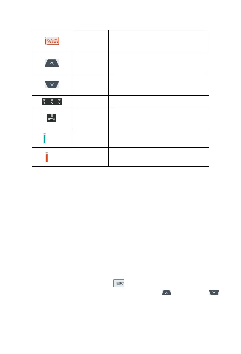
When the keyboard control is enabled, press this key
to stop the inverter.
When the inverter fails, press this key to reset the
fault.
Increment in function code, menu group or parameter
setting.
Increase the currently valid reference digital input
data.
Decrement the function code, menu group or
parameter setting.
Decrease the currently valid reference digital input
data.
It is ON when the frequency, current, and voltage are
displayed.
Running direction
indicator
This indicator is ON during reverse running. It is OFF
during forward running.
It is ON when a certain frequency is being monitored
or displayed.
It is ON when the inverter is running, flickering when
the inverter is being stopped, and OFF after the
inverter is stopped.
It turns red when the inverter is in a fault status.
4.2 Operation Mode of Keyboard with Digital Tube Display
The LED keyboard menu is divided into the monitoring level (Level 0), menu mode
selection level (Level 1), function code selection level (Level 2) and parameter level (Level
3) from low to high. The menu levels mentioned below are represented by numbers.
There are five parameter display modes: menu mode (
--A--
), used to display all
function codes; user-defined mode (
--U--
), used to display only function codes selected by
the user based on the F11 group; non-default mode (
--C--
), used to display only the
function codes that differ from the default settings; fault information display mode (
--E--
),
used to display the current fault information; and version information mode (
--P--
), used
to display the software and product serial number.
When the keyboard is powered on, the first monitoring parameter of Level 0 is
displayed by default. Press the ESC key to enter the Level 1 menu. In the Level 1
menu, you can select different menu modes via the increment and decrement
keys on the keyboard. The process of menu mode selection is shown in Fig. 4-2.
 Loading...