User Manual of A90 Series Inverter
61
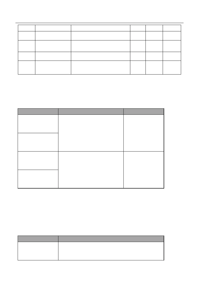
Lower frequency limit F00.19
to maximum frequency F00.16
0.00 to upper frequency limit
F00.18
0: Allow forward/reverse
running
1: Prohibit reversing
Note: Common process parameters may also include the input and output function settings.
Refer to the F02 and F03 groups in the function table.
5.7 Motor Parameter Identification
For the better control performance, motor parameters must be identified.
F01.34=01
Static self-learning
of asynchronous
motor
It is applied where the motor and
load cannot be separated easily and
rotary self-learning is not allowed.
F01.34=11
Static self-learning
of synchronous
motor
F01.34=02
Rotary self-learning
of asynchronous
motor
It is applied when the motor and
load can be separated easily. Before
operation, the motor shaft should
be separated from the load. The
motor under load must not be put
into rotary self-learning.
F01.34=12
Rotary self-learning
of synchronous
motor
Prior to self-identification, make sure that the motor is stopped; otherwise,
self-identification cannot be performed properly.
5.7.1
Parameter identification steps
Where the motor and load can be separated, the mechanical load and motor should be
completely separated in the power-off status.
After the power-on, set the command source of the inverter to keyboard control
(F00.02=0).
Enter the nameplate parameters of the motor accurately.
F01.00: Motor type F01.01: Rated power of motor
F01.02: Rated voltage of motor F01.03: Rated
current of motor
F01.04: Rated frequency of motor F01.05: Rated
 Loading...