- 102 -
No.EX##-OMY0004
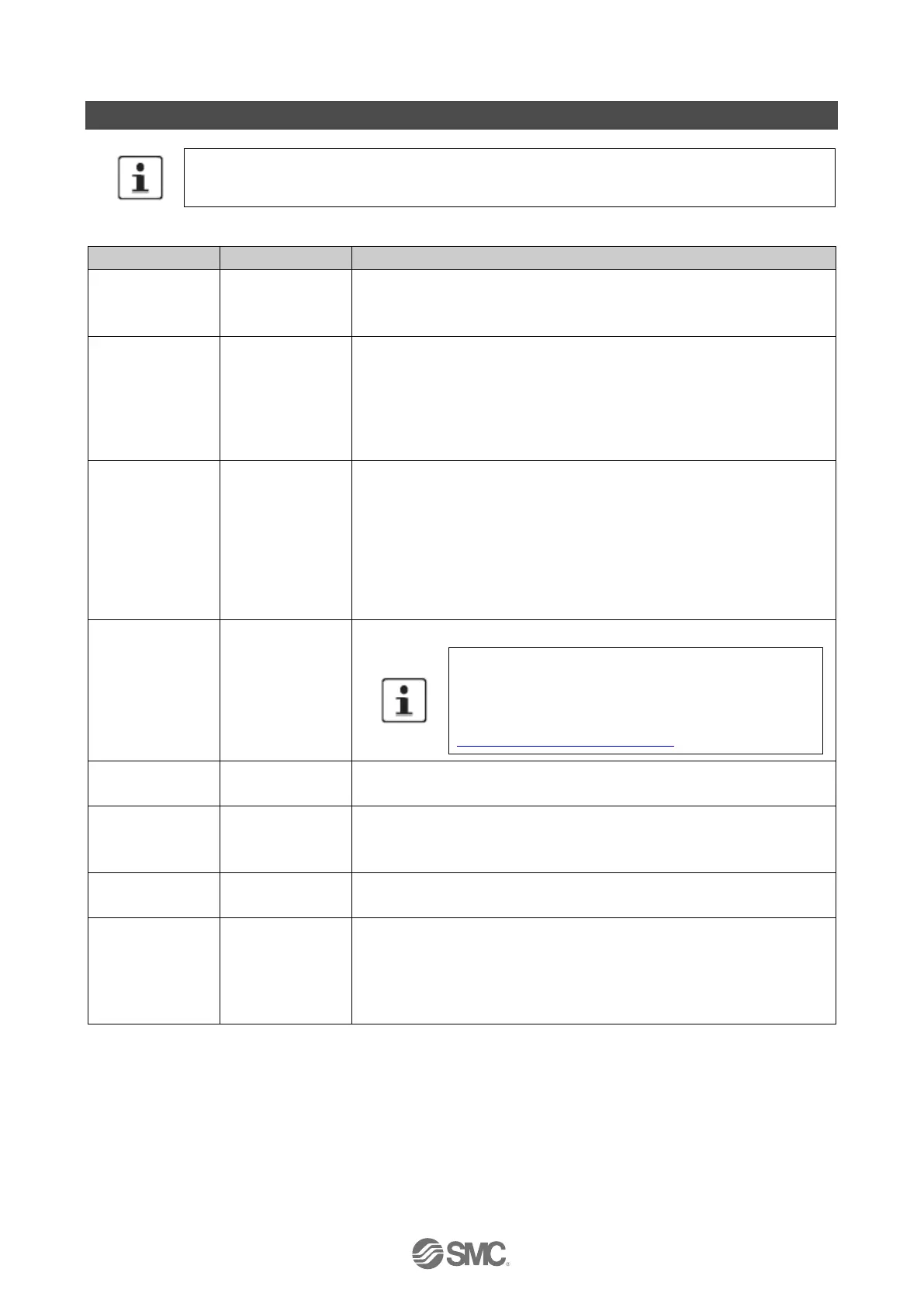
18. Appendix B: F-Parameters
The values indicated in italics in Table are preset by the system and cannot be modified
manually.
Table 19-1 Overview of the F-Parameters for the module
The parameter uniquely identifies the PROFsafe source address (controller
address).
The address is assigned automatically.
PROFIsafe destination address (address of the safe module).
The address is assigned automatically. However, the value can be
modified. Ensure each individual device is assigned a unique address
Make sure that the value set under F_Destination_Address is the same as
the value that you have set via the 10-pos. DIP switch.
Value range: 1 … 1023
Monitoring time in the module.
A valid current safety telegram must arrive from the safe controller during
the monitoring time. Otherwise the module enters the safe state.
The selected monitoring time must be sufficiently high for telegram delays
to be tolerated by the communication, but still ensure a sufficiently fast error
response in the event of an error (e.g., interruption in communication).
Value range: 1 … 10000, in 1 ms increments
Unit: ms
Safety integrity (SIL according to IEC61508) of the module.
Safety functions up to SIL 3 can be achieved with the
module. The safety integrity level that can actually be
achieved depends on the parameterization, the structure
of the sensor, and the cable installation:
See Section 8.2 “Parameterisation”.
This parameter transmits the length of the CRC2 code to be expected in
the safety telegram to the safe controller.
Parameter block type identification.
1: the parameter block of the F-Parameters contains the F_iPar_CRC
parameter.
Version number of the F-Parameter block.
1: valid for V2 mode.
CRC checksum via the i-Parameters.
The value must be greater than 0.
When verifying the safety function, check whether the F_iPar_CRC
parameter is greater than 0 for all modules. IF not, check the i-Parameters
and the CRC checksum in the i-Parameter and F-Parameter.

 Loading...

