- 17 -
No.EX##-OMY0004
3.3.5. Clock outputs UT1 and UT2
The module has two independent clock outputs. These clock outputs provide the supply voltage for the
safe inputs. Both clock outputs provide a pulse pattern to detect cross circuits in the external wiring of the
inputs if Cross circuit detection has been activated for at least one input pair.
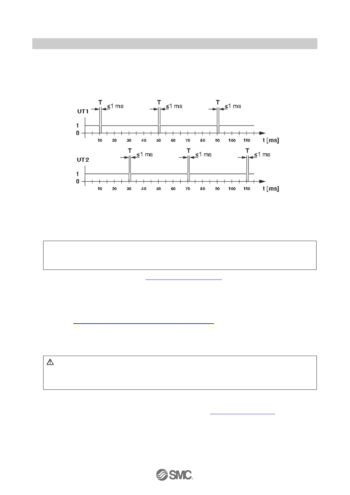
3.3.6. Typical pulse pattern
Fig. 3-2 Typical pulse pattern
Key:
T Test pulse
Pulse width ≤ 1 ms
Period length ≤ 40 ms
The clock outputs are also switched on and monitored when the module is not parameterized.
If a short circuit occurs between UT1 (or UT2) and 0V (US1), the relevant clock output is switched off.
The fault state is indicted by the illumination of the UT1 (or UT2) LED.
Note a cross circuit fault on either UT1 (and/or UT2) will not affect the state of the relevant clock output
Technical data for the clock outputs: see Section 10.2 “Specifications”.
Behaviour in the event of an error
In the event of short circuit to GND or overload of the clock outputs, the clock outputs are switched off. At
the same time, the error is indicated at the UT1/UT2 LEDs and a diagnostic message is generated at the
controller. This error must be acknowledged so that the system can be started up again following error
removal, see Section 16.3 “Acknowledging an error for PROFIsafe”.
As there are two clock outputs for eight inputs, there may be reciprocal effects between the inputs.
Diagnostics
WARNING: Loss of safety function
Using diagnostic data for safety-related functions can result in the loss of the safety function as
diagnostic data is not safety-related.
Do not use the diagnostic data for safety-related functions or actions.
Diagnostics are provided via both the local diagnostics indicator and the diagnostic messages which are
transmitted to the controller.
Information on the diagnostic messages of the clock outputs: see Section 20 “Appendix D”.

 Loading...

