- 38 -
No.EX##-OMY0004
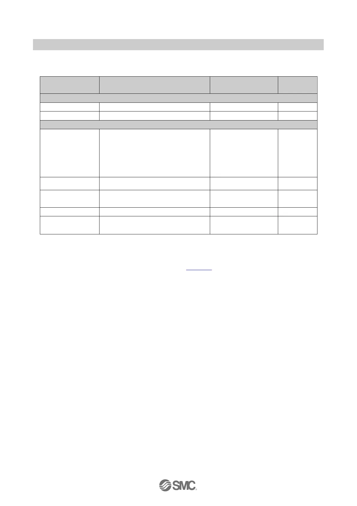
Module parameters for Safe inputs parameter details in Safety Mode (Channel Passivation)
Table 8-4 Safe inputs parameter details in Safety Mode (Channel Passivation)
Disable
1-out-of-2 evaluation (2-channel equivalent)
1-out-of-2 evaluation (2-channel non-
equivalent)
1-out-of-1 evaluation (Input N)
1-out-of-1 evaluation (Input N+4)
1-out-of-1 evaluation (Input N, N+4)
Disable, 10 ms, 50 ms, 100 ms, 1 s, 5 s
Note: Parameter “Filter time” and “Power source for cross-circuit detection” are valid when “Sensor evaluation” is other than
“Disable”
Parameter “Discrepancy time” and “Start inhibit after discrepancy” are evaluated only if the “Sensor evaluation” is one of
the “1oo2 2-channel” evaluation.
For Safety Mode (Module Passivation/xxx), please refer to section 10.6 for details on how to configure the parameters.
The following gives some additional explanation for the parameters for the safe inputs.
Sensor power supply (Clock configuration)
This parameter is for activation of the clock pulse of the sensor power supply UT1 and UT2.
A cross-circuit of a sensor can only be detected when the clock pulse is set to "enable."
Power source for cross-circuit detection
This parameter specifies which power supply (UT1 or UT2) is used for the sensor.
A cross-circuit of a sensor can only be detected if the clock pulse is enabled for the specified power
supply.
The device can perform a cross-circuit test simple sensors, for example, a 2-wire sensor with reed
contact switch. It is not suitable for sensors with internal electrical logic circuit, for example a 3-wire
sensor with a transistor output.

 Loading...

