- 63 -
No.EX##-OMY0004
10.9.1.4. L/A indicator
Table 10-22 L/A indicator
Connection via Ethernet to the SI Unit via Port 1/2 (XF1/2)
No connection established via Port 1/2 (XF1/2)
Transmission or reception of Ethernet telegrams on Port 1/2 (XF1/2)
No transmission or reception of Ethernet telegrams on Port 1/2 (XF1/2)
Received Node flash request
: When Link LED and Act LED are both on the combined colour may appear to be orange
10.9.1.5. FO 1/2 Indicator
Table 10-23 FO 1/2 indicator
The strength of the Fibre-Optic communication is more than 2 dB.
The strength of the Fibre-Optic communication is more than 0 dB but less than 2 dB.
The strength of the Fibre-Optic communication is less than 0 dB.
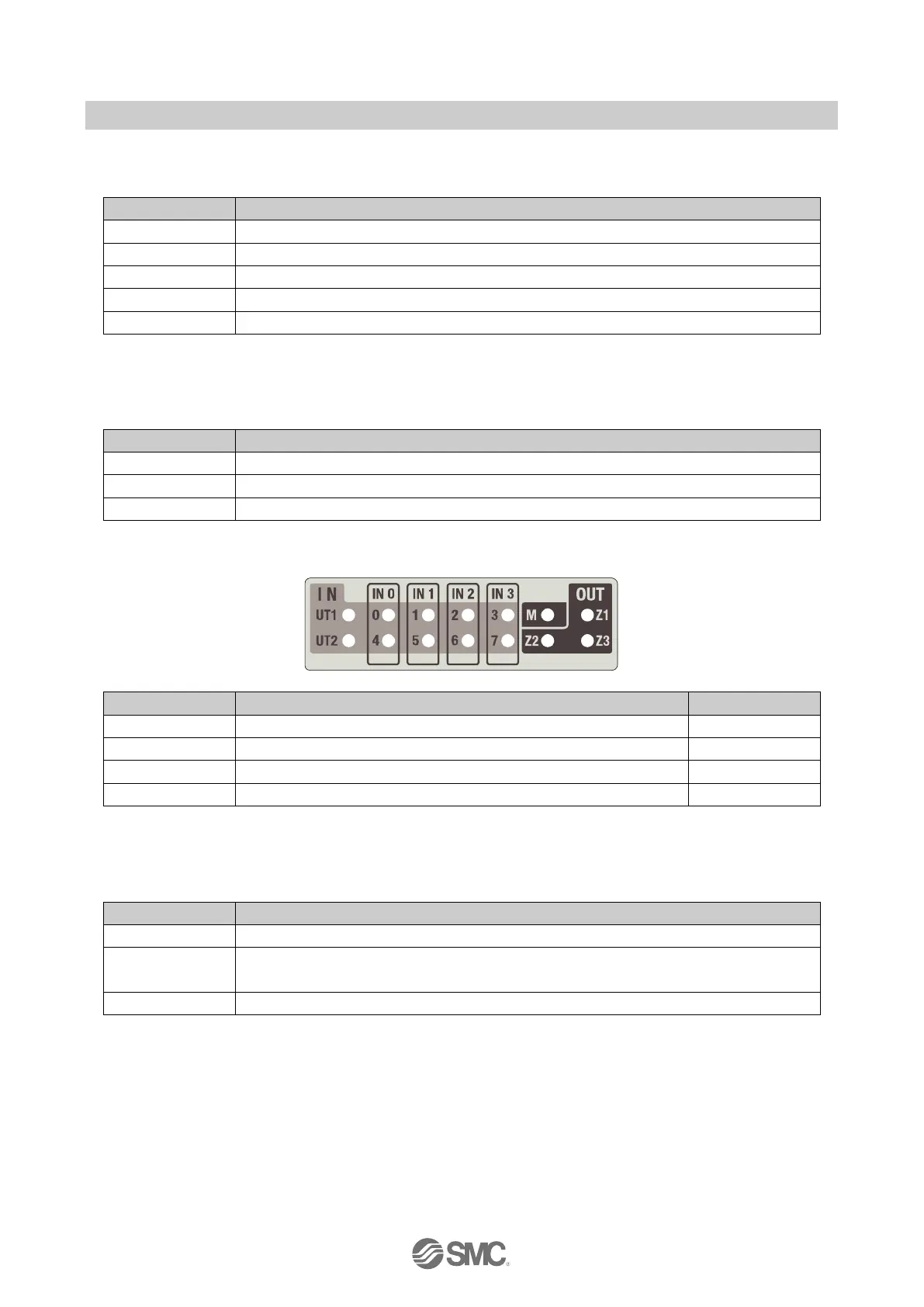
Status for the clock power supply UT1 and UT2
Status for safe US2 power supply for IO modules
Status for safe US2 zone power supplies for valves
Fig. 10-4 LED indicators 2 of the EX245-FPS1/2/3
10.9.2.1. UT1 and UT2 LEDs
Table 10-24 UT1 and UT2 LEDs
At least one of the safe inputs has a cross circuit with another signal (e.g. the other safe
input, 24 V or an external signal)
The clock power supply has a short circuit or overload.

 Loading...

