-13-
No.PF※※-OMJ0006-G
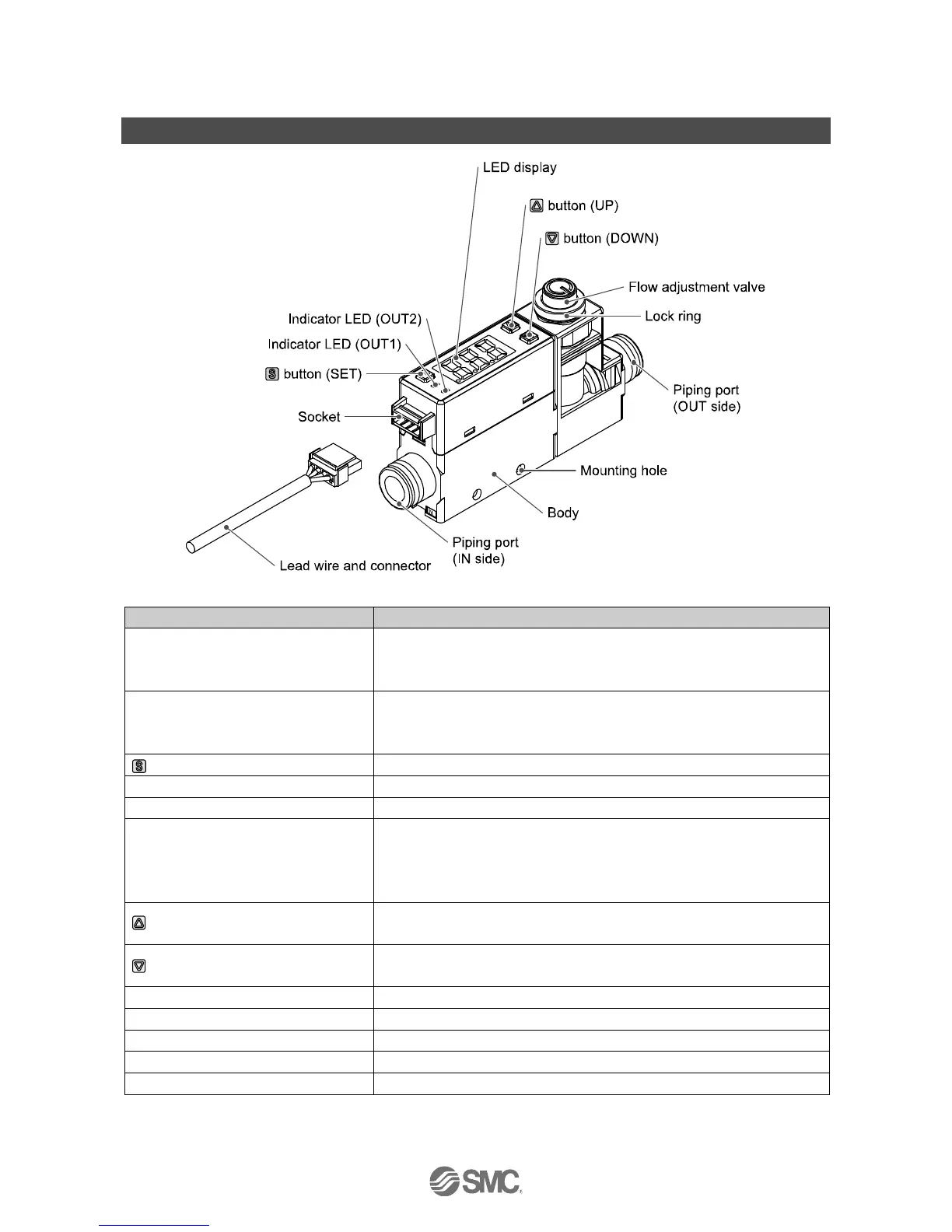
Summary of Product parts
Indicates the output status of OUT1. LED is ON (Green) when OUT1 is ON.
When the accumulated pulse output mode is selected, the indicator LED will
turn OFF.
Indicates the output status of OUT2. LED is ON (Red) when OUT2 is ON.
When the accumulated pulse output mode is selected, the indicator LED will
turn OFF.
Press this button to change to another mode and to set a value.
Socket for electrical connections.
Connected to the fluid inlet at IN side and to the fluid outlet at OUT side.
Displays the flow value, setting mode, and error indication.
Four display modes can be selected: display always in red or green, or
display changing from green to red, or red to green, according to the output
status (OUT1).
Selects the mode or increases the ON/OFF set value.
Press this button to change to the peak display mode.
Selects the mode or decreases the ON/OFF set value.
Press this button to change to the bottom display mode.
Orifice mechanism to adjust the flow.
Used to lock the flow adjustment valve.
Used to mount the product on a DIN rail or directly to a panel.
Lead wire to supply power and transmit output signals.
: The table shows the specifications when a flow adjusting valve is included.
 Loading...