Configuring the Switch
3-146
3
The priority levels recommended in the IEEE 802.1p standard for various network
applications are shown in the following table. However, you can map the priority
levels to the switch’s output queues in any way that benefits application traffic for
your own network.
Command Attributes
• Priority – CoS value. (Range: 0-7, where 7 is the highest priority)
• Traffic Class
10
– Output queue buffer. (Range: 0-3, where 3 is the highest CoS
priority queue)
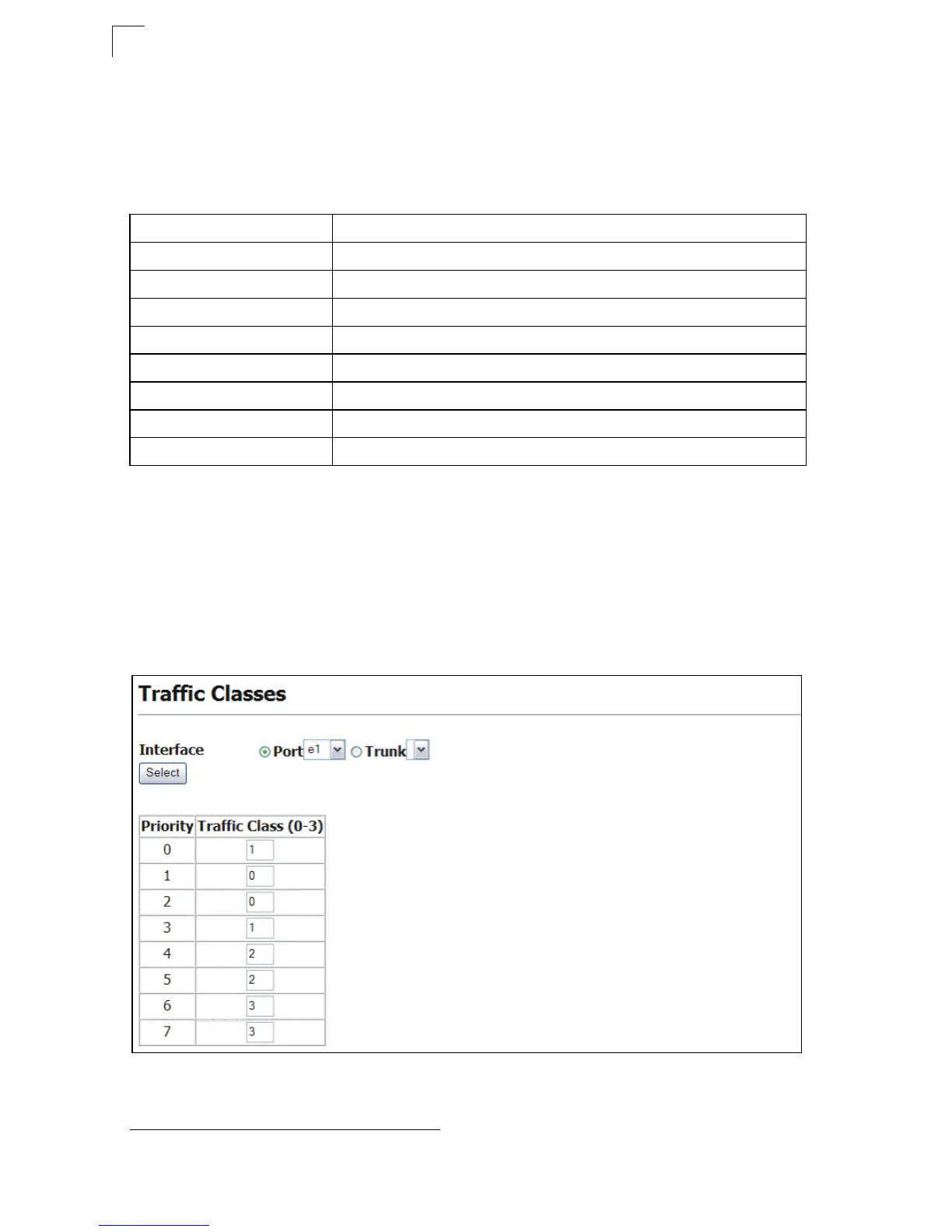
Web – Cli
ck Priority, Traffic Classes. Select a port or trunk for the current mapping of
CoS values to output queues to be displayed. Assign priorities to the traffic classes
(i.e., output queues), then click Apply.
Figure 3-85 Traffic Classes
Table 3-12 CoS Priority Levels
Priority Level Traffic Type
1Background
2 (Spare)
0 (default) Best Effort
3 Excellent Effort
4 Controlled Load
5 Video, less than 100 milliseconds latency and jitter
6 Voice, less than 10 milliseconds latency and jitter
7 Network Control
10. CLI shows Queue ID.
 Loading...