Since each source has its own “maintenance bypass”, two cases may be considered:
a. Inverter Q50 is set to position I (or Q51 on 1 for Statys 800/1000A):
– Close Q41,
– switch conduction onto source 1
– visually check, according the display, that the green LED of static switch 1 is lit (type D20, see 7.1.2), or
the colour of the bar on the diagram animation (type: ADICOM, see 7.2.1-4).,
– once the LED is lit, close Q30,
– set Q50 to position “0” (or Q51 on 0 for Statys 800/1000A),
– also close Q42 to enable a further changeover.
b. Inverter Q50 is set to position II (or Q52 on 1 for Statys 800/1000A):
– Close Q42,
– switch conduction onto source 2,
– visually check, according the display, that the green LED of static switch 2 is lit (type D20, see 7.1.2), or
the colour of the bar on the diagram animation (type: ADICOM, see 7.2.1-4),
– once the LED is lit, close Q30,
– set Q50 to position “0” (or Q52 on 0 for Statys 800/1000A),
– also close Q41 to enable a further changeover.
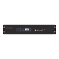
9. COMMUNICATION INTERFACE
STATYS is equipped as standard with:
– one Ethernet port which allows for ModBus TCP communication, the use of the SNMP protocol, the sending of
E-mails following alarm activation, and integrated Web page browsing
– one terminal block giving access to:
•
1 dry contact relay for the general alarm
•
1 dry contact relay for the preventive maintenance alarm
•
1 inputs for an emergency stop button (button not supplied)
•
2 outputs for accidental tripping of upstream protection (source 1 and source 2) (see § 8.6.1 on the installation
manual)
STATYS is also equipped with 4 spare slots which can each house one communication module:
– 1 serial port (JBus/ModBus or Probus or DeviceNet) on slot 1 only,
– 1 to 4 alarm relay modules (each module providing 3 inputs and 4 outputs).
10. ADVANCED DIAGNOSTICS AND PARAMETERS
STATYS is equipped with a diagnostic card for connection to a maintenance computer. This link can be used for ad-
justing the advanced parameters and other settings according to specic operational needs. Maintenance personnel
can also use this link to download the event log, statistics and comprehensive information for rapid and complete
diagnostics
 Loading...