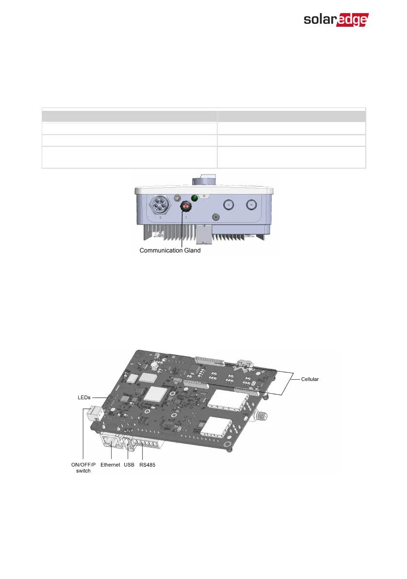
Communication Connectors
A communication gland with multiple openings is used for connection of the various
communication options. The table below describes the functionality of each gland
opening. Unused openings should remain sealed.
Opening for cable size (diameter) Connection type
2.5 - 5 mm RS485
4.5 - 7 mm, with cut Ethernet (CAT5/6)
2 - 4 mm, with cut
Antenna cable for wireless
communication
Figure 20: Communication Gland
The communication board has a standard RJ45 terminal block for Ethernet connection,
a 6-pin terminal block for RS485 connection, and an 8-pin connector for power control
devices.
The CellularPlug-in can be connected to the communication board for optional
wireless connection.
Figure 21: Communication board connectors
EV Charging Single Phase Inverter Guide MAN-01-00588-1.1
60 Communication Connectors
 Loading...