 Loading...
Do you have a question about the Sony CYBER-SHOT DSC-F717 and is the answer not in the manual?
| Sensor Type | CCD |
|---|---|
| Effective Pixels | 5.0 megapixels |
| Optical Zoom | 5x |
| Digital Zoom | 2x |
| Aperture Range | f/2.0 - f/2.4 |
| LCD Screen Size | 1.8 inches |
| LCD Screen Resolution | 123, 000 pixels |
| Viewfinder | Electronic |
| Image Sensor Size | 2/3 inch |
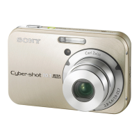
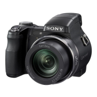
| Lens Type | Carl Zeiss Vario-Sonnar |
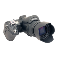
| Camera Type | Digital Still Camera |
| ISO Sensitivity | 100, 200, 400 |
| Storage Media | Memory Stick |
| Battery Type | NP-FM50 |
| Focal Length | 9.7 - 48.5 mm |
| Focus Range | 2 cm (macro) |
Guidelines for handling flexible cables and connectors during repair.
Procedure to safely discharge high-voltage capacitors before servicing.
Precautions for handling the laser diode to prevent electrostatic damage.
Explanation of the camera's self-diagnosis function and error codes.
Step-by-step guide for disassembling the rear cabinet.
Instructions for removing and disassembling the Electronic Viewfinder.
Steps to access and remove the PD-179 board.
Procedure for disassembling the LCD screen assembly.
Guide for disassembling the AL-013 board and DC-IN jack.
Steps to access and remove the SW-379 control switch board.
High-level functional overview of the camera system (part 1).
High-level functional overview of the camera system (part 2).
High-level functional overview of the camera system (part 3).
Power distribution and control overview (part 1).
Power distribution and control overview (part 2).
Overall schematic representation of major component connections.
Detailed circuit schematics for various boards and units.
Layout diagrams showing component placement on circuit boards.
Oscilloscope waveform examples for key test points on specific boards.
Visual guide to the physical location of components on circuit boards.
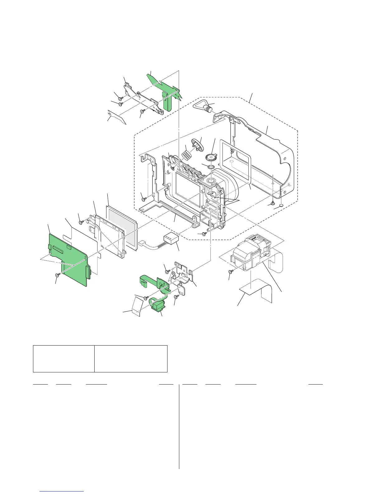
Illustrated breakdowns of major assemblies with part references.
Comprehensive list of electrical components with part numbers and descriptions.