5-7
DCR-HC40/HC40E
5. REPAIR PARTS LIST
5. REPAIR PARTS LIST
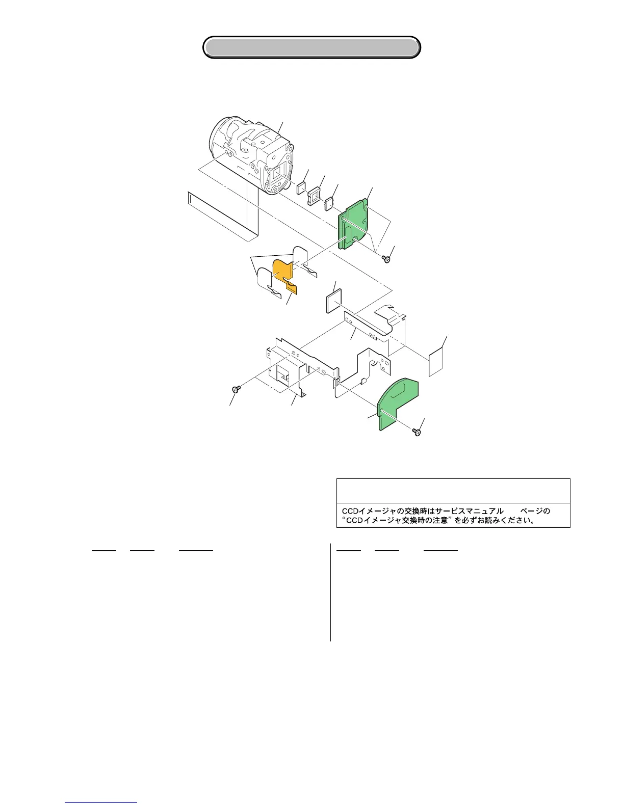
5-1-5. LENS SECTION
201 3-084-523-11 SCREW (M1.7 EG LOCK (BLACK))
202 A-7112-151-A SE-141 BOARD, COMPLETE
203 3-089-525-01 FRAME (G), LENS
204 3-080-204-01 SCREW, TAPPING, P2
205 3-089-527-01 HEAT SINK (G), CD
206 3-089-526-01 SHEET (G), CD RADIATION
207 1-861-181-11 FP-828 FLEXIBLE BOARD
208 3-090-165-01 SHEET, RADIATION
209 3-080-204-21 SCREW, TAPPING, P2
210 A-7112-117-A CD-490 BOARD, COMPLETE
211 3-088-645-01 RUBBER (Z), SEAL
212 1-788-061-11 FILTER BLOCK, OPTICAL
213 A-7112-105-A 841A (CZ) BLOCK ASSY
214 3-091-260-01 SHEET, INSULATING, CD
IC201 A-7112-341-A CCD BLOCK ASSY (1M) (CCD IMAGER)
(IC201 is not included in this COMPLETE board.)
Ref. No. Part No. Description Ref. No. Part No. Description
Be sure to read “Precautions upon replacing CCD imager”
on page 4-5 when changing the CCD imager.
4-6
213
212
211
210
209
207
202
203
201
205
206
208
204
IC201
214
 Loading...