HCD-M40D/M60D/M80D
25
SECTION 5
TROUBLESHOOTING
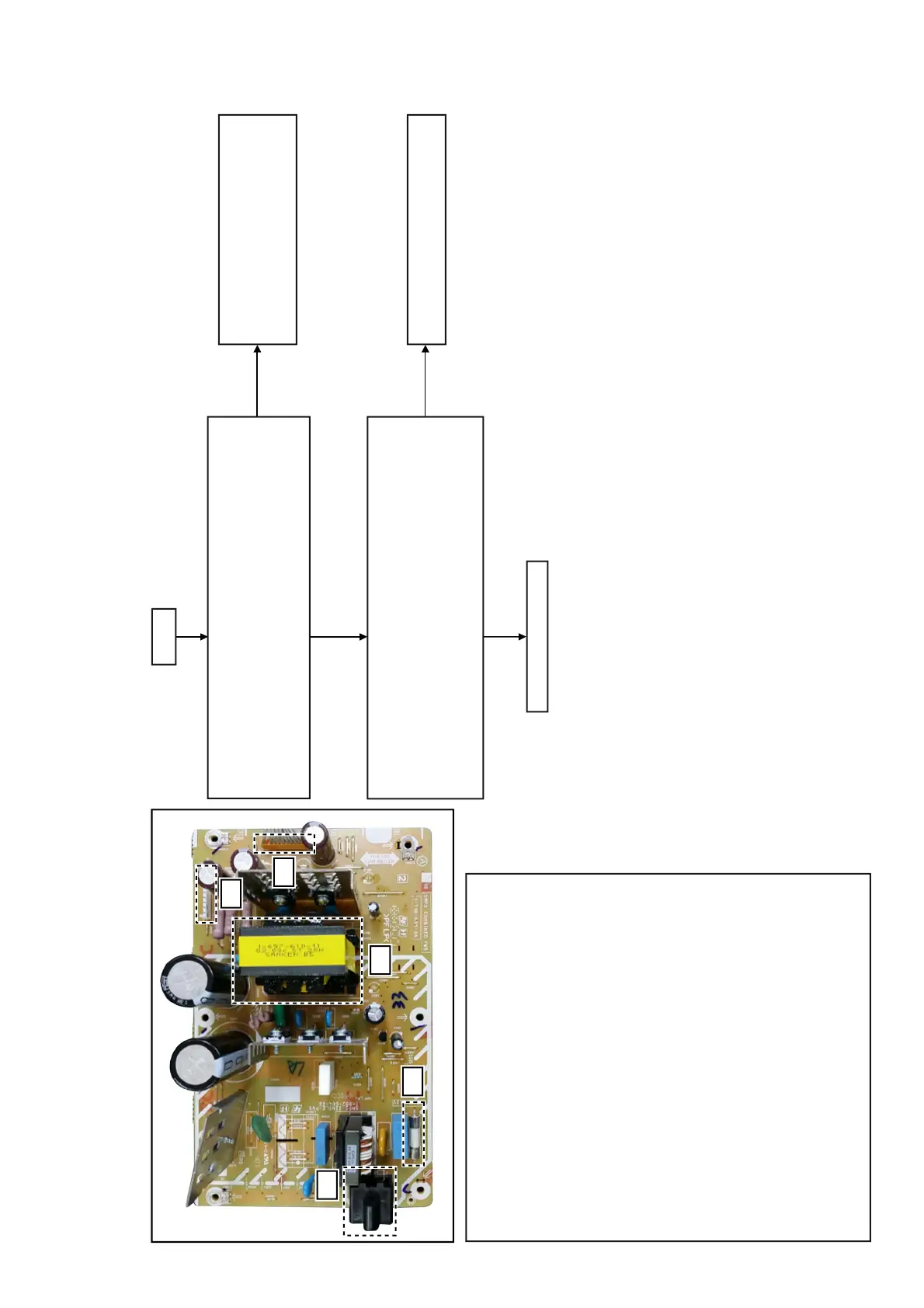
SMPS Diagnosis Flow (HCD-M40D)
The Output from SMPS board is checked.
Is following power voltage up to standard?
AC IN
Yes
No
Yes
END
No
Check whether the state of the Cable and
Outlet are normal. If there are no problems,
check circumference circuit for Main on
Output of the Motherboard mount side.
Replaces SMPS board if it is not up
to standard.
The Power Control signal to SMPS board is checked.
Is following power voltage OK?
Main on
NO6501 PIN 9
Standby
Low (0V)
Demo Mode
Hi (3.3V)
Power On
Hi (3.3V)
NO6501 PIN 1,4,5
CN6500 PIN 6,7,8,9
Standby
17.4V±5%
58.5V± 5%
Demo Mode
17.4V±5%
58.5V± 5%
Power On
17.4V±5%
58.5V± 5%
(1) AC input
(2) Fuse
(3) MAIN power transformer
(4) NO6501 connector
Pin 1 : Audio (+17V)
Pin 3 : Audio (GND)
Pin 4 : LED (+17V)
Pin 5 : LED (+17V)
Pin 6 : LED (GND)
Pin 7 : LED (GND)
Pin 8 : AC DET
Pin 9 : Main ON
Pin 10 : Network ON
Pin 11 : Latch ON
Pin 1 : PGND
Pin 3 : PGND
Pin 4 : PGND
Pin 5 : PGND
Pin 6 : PVDD (DC+58.5V)
Pin 7 : PVDD (DC+58.5V)
Pin 8 : PVDD (DC+58.5V)
Pin 9 : PVDD (DC+58.5V)
(5) CN6500 connector
(1)
(2)
(3)
(4)
(5)
 Loading...